
Array substrate, display panel and display device

An array substrate and display panel technology, applied in nonlinear optics, instruments, optics, etc., can solve problems such as poor display effect of liquid crystal display panels, achieve uniform reflection, uniform display brightness, and solve the effects of uneven wiring

Pending Publication Date: 2019-03-29
XIAMEN TIANMA MICRO ELECTRONICS
View PDF7 Cites 26 Cited by
  • Summary
  • Abstract
  • Description
  • Claims
  • Application Information

AI Technical Summary

Problems solved by technology

However, for reflective liquid crystal display panels and transflective liquid crystal display panels, other wirings arranged in the above display area will affect the display brightness of the liquid crystal display panel, thus making the picture display effect of the liquid crystal display panel poor

Method used


Image

  • Array substrate, display panel and display device
  • Array substrate, display panel and display device
  • Array substrate, display panel and display device

Examples


Embodiment Construction

[0030] The present invention will be further described in detail below in conjunction with the accompanying drawings and embodiments. It should be understood that the specific embodiments described here are only used to explain the present invention, but not to limit the present invention. In addition, it should be noted that, for the convenience of description, only some structures related to the present invention are shown in the drawings but not all structures.

[0031] figure 1 A schematic plan view of an array substrate provided in the prior art. refer to figure 1 , the array substrate 000 includes: a display area 00A and a non-display area 00N surrounding the display area 00A, display signal lines 002, fan-out area switching lines 001 and fan-out lines 003 are arranged in the display area 00A, and the display signal lines 002 and The fan-out lines 003 all extend along the second direction Y and are arranged along the first direction X. The fan-out area line-changing w...


PUM


Abstract

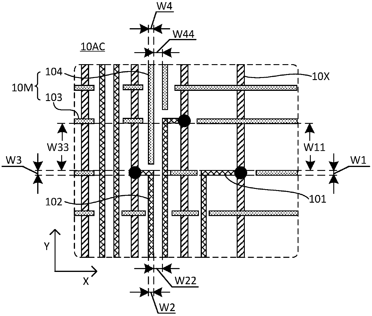
The embodiment of the invention discloses an array substrate, a display panel, and a display device. The array substrate comprises a display area, a display signal line, a first connecting line, a second connecting line and a dummy connecting line arranged in the display area, and a driving circuit arranged in a non-display area. The display signal line and the second connecting line both extend in a second direction and are arranged in a first direction. The first connecting line extends in the first direction and is arranged in the second direction. The display signal line is electrically connected with the driving circuit through the first connecting line and the second connecting line. At least one of two ends of the second connecting line extends to the non-display area. The dummy connecting line is located in a same straight line with the first connecting line or the second connecting line. At least one of two ends of the dummy connecting line extends to the non-display area. According to the array substrate provided by the embodiment of the invention, the problem of non-uniform display caused by uneven wiring of the first connecting line or the second connecting line can beavoided, so as to improve the display effect.

Description

technical field [0001] The present invention relates to display technology, in particular to an array substrate, a display panel and a display device. Background technique [0002] Liquid crystal display panels can be classified into transmissive, reflective, and transflective types according to different light sources. Wherein, in the transmissive liquid crystal display panel, the light emitted by the backlight passes through the transparent electrodes and the liquid crystal layer to display images. Reflective liquid crystal display panels can use external light sources. On the one hand, the power consumption of the entire liquid crystal display panel is low; The light energy of the eyes is low, so the reflected light does less damage to the eyes, so that the reflective liquid crystal display panel also has the advantage of eye protection. The transflective liquid crystal display panel is a combination of transmissive and reflective structures, and a transmissive area and...

Claims


Application Information

Patent Timeline
Patent Type & Authority Applications(China)
IPC IPC(8): G02F1/1362
CPCG02F1/136286
Inventor 张敏孔祥建郭浩
Owner XIAMEN TIANMA MICRO ELECTRONICS
Learn More