
Lubrication system with a signal transmission element

A lubrication system and signal transmission technology, applied in the field of lubrication systems, can solve problems such as destructive, complicated and impossible wiring of the lubrication system, and achieve the effect of fast signal transmission and simple signal transmission

Pending Publication Date: 2019-02-26
德国斯凯孚润滑油系统有限责任公司
View PDF6 Cites 3 Cited by
  • Summary
  • Abstract
  • Description
  • Claims
  • Application Information

AI Technical Summary

Problems solved by technology

[0003] However, in conventional lubrication systems, the wiring within the lubrication system is often very complex and partly destructive, which is disadvantageous
In addition, some lubrication system components or parts thereof cannot be connected to lubrication system monitoring devices or sensors, because the wiring of these lubrication system monitoring devices or sensors is not possible

Method used


Image

  • Lubrication system with a signal transmission element

Examples


Embodiment Construction

[0022] In the following, identical or functionally equivalent elements are denoted by the same reference numerals.

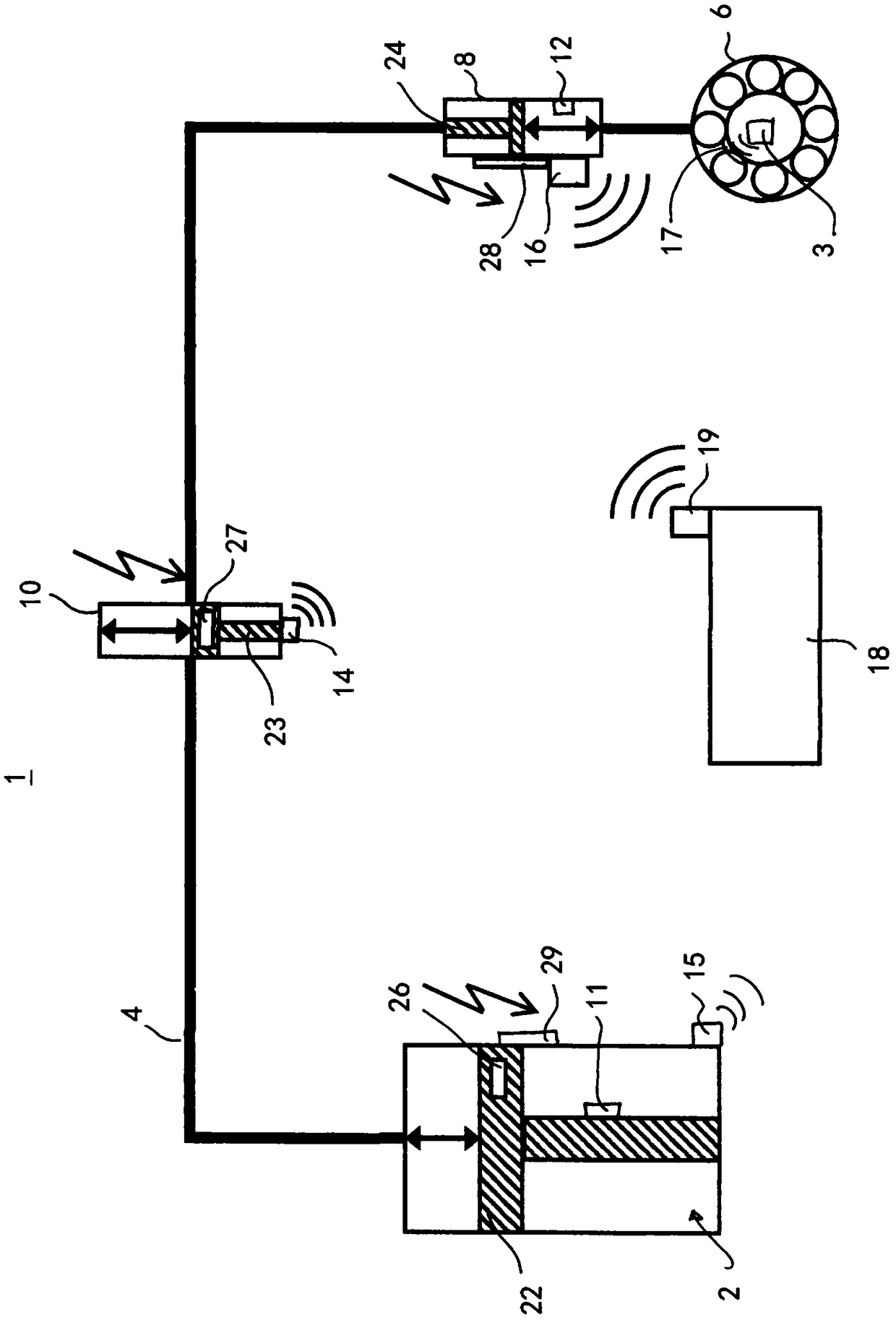
[0023] figure 1 A lubrication system 1 is schematically shown comprising a lubricant pumping arrangement 2 connected to a lubricant line 4 for pumping lubricant to points to be lubricated here described as bearings 6. In order to deliver precisely metered lubricant or to generally distribute lubricant to the bearing, a lubricant distribution device 8 arranged upstream of the bearing 6 is also provided. For example, the lubricant distribution device may be a single line dispenser or a progressive dispenser. like figure 1 As shown, the lubrication system monitoring device is also arranged on the lubricant pipeline 4 in the form of a sensor 10 , for example, the sensor 10 monitors the flow rate of the lubricant flowing through the pipeline 4 or its temperature or viscosity. exist figure 1 In the exemplary embodiment shown, the lubrication system monitoring dev...


PUM


Abstract

The invention discloses a lubrication system configured to supply a lubricant to at least one lubrication point. The lubrication system includes at least one lubricant pump configured to pump the lubricant to the at least one lubrication point, a lubricant distributor configured to distribute the lubricant at the at least one lubrication point, a control unit configured to control at least the lubricant pump and / or the lubricant distributor, at least one lubrication system monitor configured to monitor a monitoring variable of the lubrication system, and at least one signal transmission deviceconfigured to wirelessly transmit a signal indicative of the monitoring variable provided by the lubrication system monitor to the control device or to receive signals therefrom.

Description

technical field [0001] The present invention relates to a lubrication system for supplying lubricant to at least one lubrication point, wherein the lubrication system comprises: at least one lubricant pumping device, which pumps lubricant in the lubrication system to the lubrication point; Dispensing means, which distribute lubricant at said lubrication points; and control means, which control at least the lubricant pumping means and / or the lubricant dispensing means. Background technique [0002] Lubrication systems are available in various designs to provide lubricant at the points to be lubricated. Wherein, the lubrication system usually includes a lubricant pumping device, such as a lubricant pump and a lubricant pipeline, and the lubricant is pumped from the lubricant pumping device to the point to be lubricated through the lubricant pipeline. Furthermore, a lubricant distribution device is provided at the point to be lubricated, wherein the lubricant distribution devi...

Claims


Application Information

Patent Timeline
IPC IPC(8): F16N13/22F16N29/02G08C17/00
CPCF16N13/22F16N29/02G08C17/00F16N7/385F16C33/66F16N2210/14F16N2230/00F16N2250/00F16N2260/02F16N29/04H02J7/00F16N7/38F16N13/02F16N2250/04F16N2250/18F16N2250/40F16N2270/70H01F7/06H02N2/18
Inventor J.克罗伊茨肯珀H.施密特A.舍恩菲尔德
Owner 德国斯凯孚润滑油系统有限责任公司
Learn More