
A current-limiting automatic regulator for motor

A regulator and motor controller technology, applied in AC motor control, electrical components, control systems, etc., can solve problems such as poor current limiting effect, lack of pertinence, fixed current limiting value, etc., to improve reliability and safety performance, improve accuracy, and avoid motor damage

Active Publication Date: 2020-02-18
江苏开璇智能科技有限公司
View PDF4 Cites 0 Cited by
  • Summary
  • Abstract
  • Description
  • Claims
  • Application Information

AI Technical Summary

Problems solved by technology

[0004] In order to increase the current limiting value of the controller, a controller with a large current limiting value is usually used in the prior art, but this kind of controller with a large current limiting value is expensive, and the current limiting value is fixed, not targeted, and the current limiting effect is not good

Method used


Image

  • A current-limiting automatic regulator for motor
  • A current-limiting automatic regulator for motor

Examples


Embodiment Construction

[0030] The present invention will be further described in detail below in conjunction with the accompanying drawings, so that those skilled in the art can implement it with reference to the explanatory text.

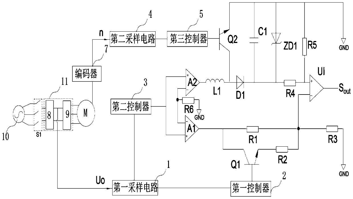
[0031] like figure 1 As shown, the present invention provides a current limiting automatic regulator for motors, wherein:

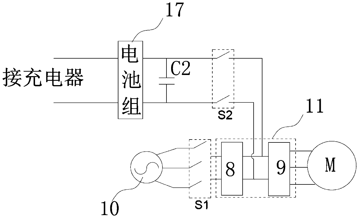
[0032] The input end of the first sampling circuit 1 is connected to the DC positive busbar of the motor power drive unit 11 for collecting the DC bus voltage Uo on the power drive unit 11. The power drive unit 11 includes a rectifier module 8 and an inverter module 9. The power drive The input terminal of the unit 11 is connected to the three-phase AC power supply 10 through the first switch group S1, and the output terminal of the power drive unit 11 is connected to the input terminal of the motor power supply. In a normal state, the three-phase AC power supply 10 supplies power to the motor through the power drive unit 11, and the power The driv...


PUM


Abstract

The invention discloses a current-limiting automatic regulator for a motor, comprising a first sampling circuit; a first controller; a second controller; a second sampling circuit; a voltage dividing circuit; a boosting circuit; and a comparator; The first output terminal of the second controller is connected to the non-inverting terminal of a first voltage amplifier, the second output terminal of the second controller is connected to the non-inverting terminal of a second voltage amplifier, and the output terminal of the second voltage amplifier is connected to the first terminal of the inductor , the output end of the first voltage amplifier is connected to the first end of the first resistor. The invention adjusts the current limiting value of the motor in real time according to the motor speed and DC voltage, thereby improving the reliability of the motor operation.

Description

technical field [0001] The invention relates to the technical field of motor control, in particular to a current-limiting automatic regulator for motors. Background technique [0002] During the operation of the motor, the operating current sometimes exceeds the safe range of the system, resulting in malfunction or damage to the motor. For this reason, a current-limiting controller is usually installed in the motor controller, in order to limit the operating current within the safe range of the system . [0003] When the controller is working, it is not always in the current limiting state, only when the working current of the motor is greater than the current limiting value, the controller will limit the current. Generally, in the following situations, the working current of the motor will exceed the range. The first situation is in the acceleration stage of the motor, and the motor speed is very low, resulting in a large working current of the motor; the second situation ...

Claims


Application Information

Patent Timeline
Patent Type & Authority Patents(China)
IPC IPC(8): H02P27/06
CPCH02P27/06
Inventor 储建华韦汉培王刚扶文树
Owner 江苏开璇智能科技有限公司
Learn More