
Locking mechanism of strut device

A technology of rod device and locking rod, which is applied in the chassis and other directions, can solve problems such as accidental unlocking, great influence on thread quality, and complicated thread force form, etc., and achieve the effect of reliable and stable structure and stable locking function

Active Publication Date: 2019-01-29
SHENYANG AIRCRAFT DESIGN INST AVIATION IND CORP OF CHINA
View PDF5 Cites 0 Cited by
  • Summary
  • Abstract
  • Description
  • Claims
  • Application Information

AI Technical Summary

Problems solved by technology

[0002] The load-bearing structure of common struts or retractable actuators is often connected by threads. The force of the threads is complicated, and the manufacturing process has a great influence on the quality of the threads. Moreover, active locking cannot be realized, and it will be damaged after locking. Risk of unintentional unlocking due to pressure pulses or overloads

Method used


Image

  • Locking mechanism of strut device
  • Locking mechanism of strut device
  • Locking mechanism of strut device

Examples


Embodiment Construction

[0037] In order to make the objectives, technical solutions and advantages of the present invention clearer, the technical solutions in the embodiments of the present invention will be described in more detail below in conjunction with the drawings in the embodiments of the present invention. In the drawings, the same or similar reference numerals denote the same or similar elements or elements having the same or similar functions throughout. The described embodiments are some, but not all, embodiments of the invention. The embodiments described below by referring to the figures are exemplary and are intended to explain the present invention and should not be construed as limiting the present invention. Based on the embodiments of the present invention, all other embodiments obtained by persons of ordinary skill in the art without making creative efforts belong to the protection scope of the present invention. Embodiments of the present invention will be described in detail b...


PUM


Abstract

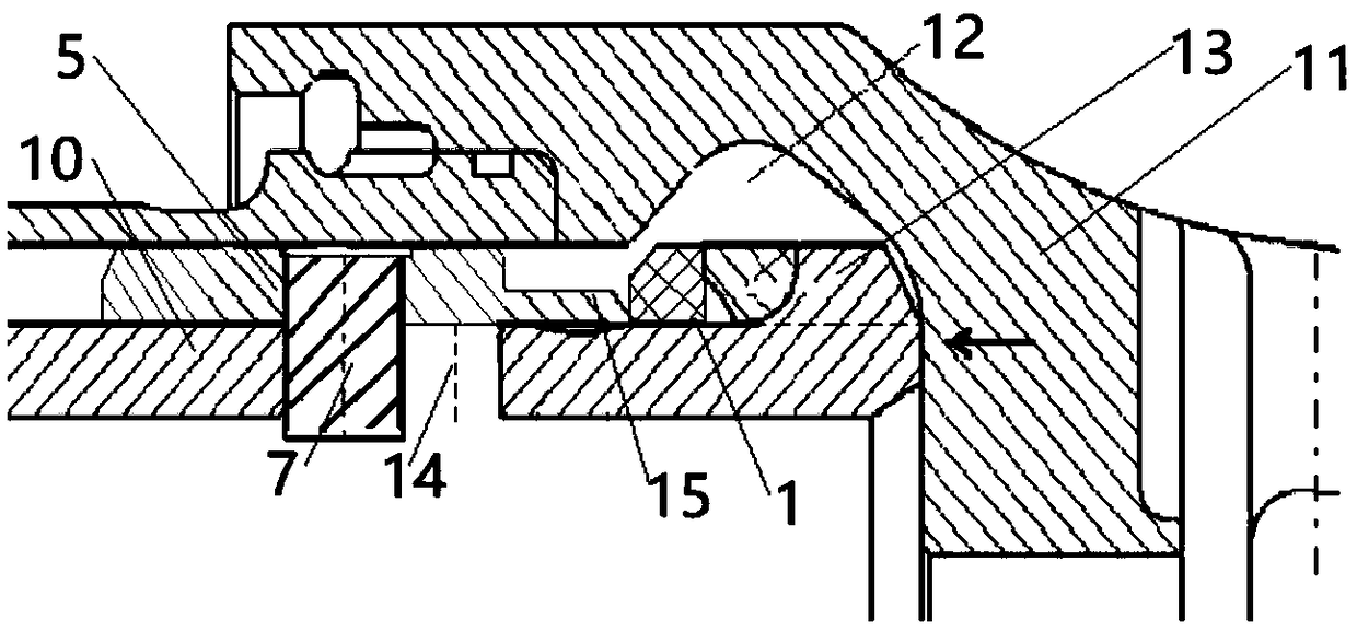
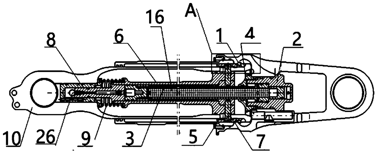
The invention relates to a strut design, in particular to a locking mechanism of a strut device. According to the invention, the inner wall of a sleeve structure of an end cover is provided with a first ring groove; one end of a piston rod is installed in the sleeve structure of the end cover; a lock rod sleeve is axially installed in the cavity of the piston rod; one end of lock rod is installedin the lock rod sleeve and is capable of performing relative movement in an axial direction, and the other end of lock rod is fixedly mounted in the end cover; a support bush sleeves the piston rod; one end, close to a limiting ring, is provided with an annular notch; the support bush is fixed on the lock rod by a pin and can move axially with the lock rod; a snap ring has a locked state and an unlocked state; when the support bush moves towards the limiting ring, the snap ring is squeezed to the annular notch, and the annular notch, the limiting ring and the first ring groove clamp the snap ring, so the snap ring is in the locked state; and when the support bush moves away from the limiting ring, the snap ring is separated from the annular notch and tightly sleeves the piston rod, so thesnap ring is in the unlocked state.

Description

technical field [0001] The invention relates to a strut design, in particular to a locking mechanism of a strut device. Background technique [0002] The load-bearing structure of common struts or retractable actuators is often connected by threads, and the force of the threads is complicated. The manufacturing process has a great influence on the quality of the threads. Moreover, active locking cannot be realized, and it will be damaged after locking. Risk of unintentional unlocking due to pressure pulses or overloads. [0003] Therefore, it is desirable to have a technical solution to overcome or at least alleviate at least one of the above-mentioned drawbacks of the prior art. Contents of the invention [0004] The object of the present invention is to provide a locking mechanism for the brace device, which is used to control the connection or disconnection of the load-bearing structure of the brace device. [0005] Technical scheme of the present invention is: [00...

Claims


Application Information

Patent Timeline
IPC IPC(8): B64C25/22
CPCB64C25/22
Inventor 李志国倪艳红姚佰栋李福苑强波
Owner SHENYANG AIRCRAFT DESIGN INST AVIATION IND CORP OF CHINA
Learn More