
Rod-shaped object recognition-based mobile robot self-positioning system

A technology for rod-shaped objects and moving objects, applied in the field of robot navigation, can solve problems such as increased cost, large processor hardware requirements, and limited application occasions, and achieves low cost, high precision, real-time performance and good robustness.

Inactive Publication Date: 2019-01-25
TONGJI UNIV
View PDF5 Cites 27 Cited by
  • Summary
  • Abstract
  • Description
  • Claims
  • Application Information

AI Technical Summary

Problems solved by technology

The disadvantage of this method is that, on the one hand, the uncertainty of the characteristics of the collected information, on the other hand, because the feature calculation and matching of point clouds or images requires a large amount of calculation, the demand for processor hardware is relatively large, and the cost is also high. will improve
[0007] The positioning scheme based on lidar or stereo camera is based on the identification and matching of road signs. The common way is to locate through the identification of traffic planning lines. The main reason for this method is that the applicable occasions are relatively limited and must be occasions with traffic planning lines. Not available on some suburban roads, maintenance roads or internal roads

Method used


Image

  • Rod-shaped object recognition-based mobile robot self-positioning system
  • Rod-shaped object recognition-based mobile robot self-positioning system
  • Rod-shaped object recognition-based mobile robot self-positioning system

Examples


Embodiment Construction

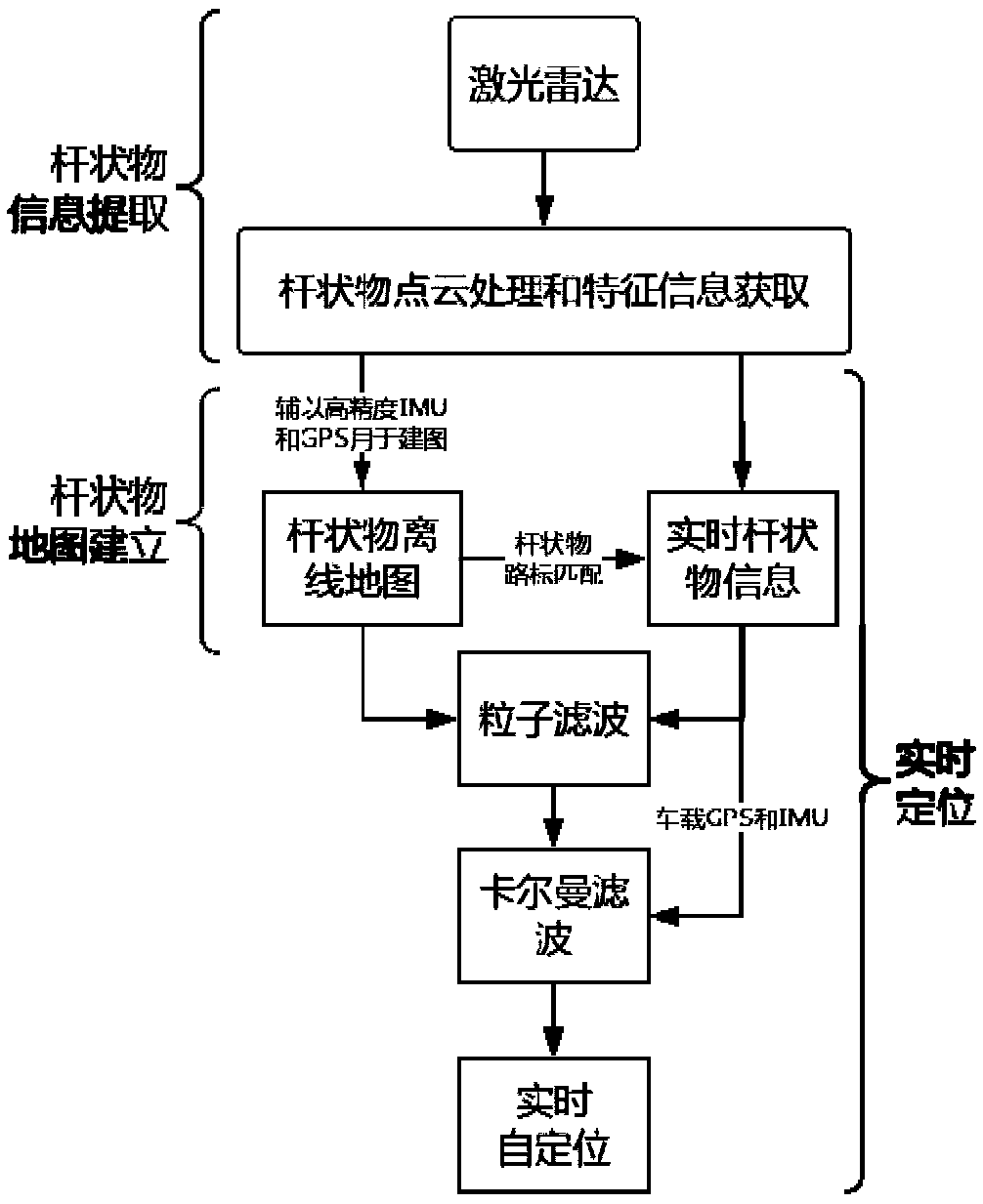
[0052] The invention provides a method for locating a moving object based on pole-shaped object recognition. The method is based on establishing pole map, extracting pole information and real-time positioning. The detailed flow chart is as follows: figure 1 shown. The method comprises the steps of:

[0053] (1) Constructing an offline map of rods;

[0054] (2), use the laser radar to obtain the point cloud data around the moving object, and extract the rod information from the point cloud data;

[0055] (3) Perform real-time positioning according to the pole-shaped object information and the pole-shaped object offline map, and obtain the positioning information of the moving object.

[0056]Wherein, the above-mentioned mobile object is a mobile vehicle or a mobile robot.

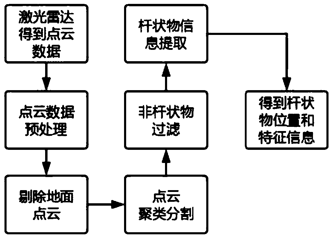
[0057] In step (1), constructing the pole-shaped object offline map includes the process of identifying the pole-shaped object. The detailed flow chart of this process is as follows figure 2 shown. Th...


PUM


Abstract

The invention discloses a rod-shaped object recognition-based mobile robot self-positioning system. According to the invention, the positioning method of the system includes the following steps that:a rod-shaped object off-line map is constructed; a laser radar is utilized to obtain point cloud data around a moving object, and rod-shaped object information is extracted from the point cloud data;and self-positioning is performed according to the rod-shaped object information and the rod-shaped object off-line map, so that the positioning information of the moving object can be obtained. According to the rod-shaped object recognition-based mobile robot self-positioning system of the invention, the laser radar is utilized to identify and track a rod-shaped object; data processing and fusionare performed through a corresponding positioning algorithm on the basis of the information of an inertial measurement unit and a GPS, and therefore, the self-positioning of the moving object can berealized. With the method of the invention adopted, positioning accuracy of a decimeter level can be realized. Capable of meeting actual application requirements, the system or the method has the advantages of low cost, high precision, real-time performance and robustness.

Description

technical field [0001] The invention belongs to the technical field of robot navigation, and relates to a self-positioning system of a mobile robot based on rod-shaped object recognition, such as a method for positioning a mobile vehicle based on rod-shaped object recognition. Background technique [0002] When navigating intelligent mobile robots or self-driving vehicles, high-precision maps are needed to reduce the uncertainty caused by perception and recognition errors and noise. At the same time, various sensors are matched with the map, and data processing is performed through corresponding algorithms. So as to obtain the accurate self-pose. [0003] The current commonly used positioning method generally uses a high-precision inertial measurement device with a differential global positioning system (INS / DGPS), but this method has the following disadvantages: [0004] First, the cost of the sensor itself is too high. A high-precision INS / DGPS system requires tens of th...

Claims


Application Information

Patent Timeline
Patent Type & Authority Applications(China)
IPC IPC(8): G01S17/06G01C21/16G01S17/93
CPCG01C21/165G01S17/06G01S17/931
Inventor 陈广叶灿波卢凡余卓平陈凯熊璐杜嘉彤许仲聪
Owner TONGJI UNIV
Learn More