A cutting machine with variable angle and variable pitch

A technology of variable pitch and unloading machine, applied in the direction of conveyor objects, transportation and packaging, etc., can solve the problems of different transfer distance and direction, unsuitable for continuous large-scale production, and inability to change products according to demand, etc., to achieve Reduced manpower input, high mechanical placement efficiency, and no jamming effects

Active Publication Date: 2020-09-25
DONGGUAN SHENGXIANG PRECISION METAL
View PDF9 Cites 0 Cited by
  • Summary
  • Abstract
  • Description
  • Claims
  • Application Information

AI Technical Summary

Problems solved by technology

[0002] In the production of 3C precision products, the problem of product transfer is frequently involved. At present, the commonly used automatic loading and unloading equipment can only transfer at the same angle and at the same distance. The transfer distance and direction may be different. At present, the equipment cannot change the distance and angle of the product according to the demand in the relatively short transfer space. Many product transfers with variable angles and pitches are done manually. The disadvantages are: First, the manual transfer of products at variable pitches and angles is very easy to scratch and damage the product; second, manual placement, especially with angle requirements, is likely to cause human error, and the accuracy of the placement position is poor, which poses hidden dangers for subsequent production and good products Third, the precision products are relatively small, the efficiency is relatively low, the labor intensity of the workers is also relatively high, and the labor cost is relatively high; Production

Method used


Image

  • A cutting machine with variable angle and variable pitch
  • A cutting machine with variable angle and variable pitch
  • A cutting machine with variable angle and variable pitch

Examples


Embodiment Construction

[0037] The present invention will be described in further detail below in conjunction with the accompanying drawings. It should be noted that the words "front", "rear", "left", "right", "upper" and "lower" used in the following description refer to the directions in the drawings, and the words "inner" and "outer" ” refer to directions towards or away from the geometric center of a particular part, respectively.

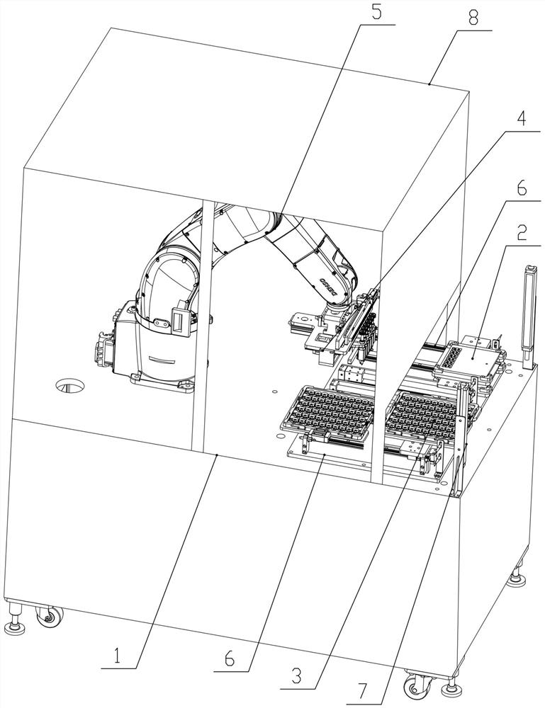
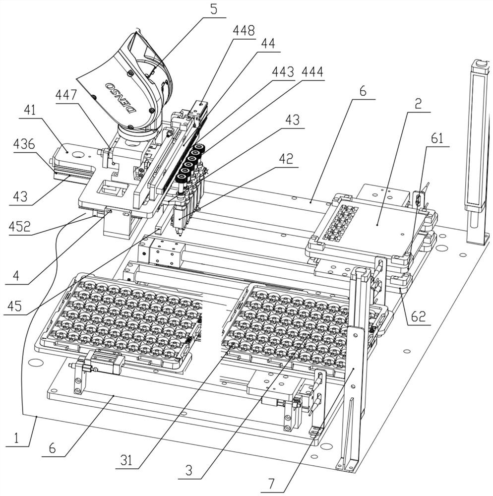
[0038] Figure 1 to Figure 8A blanking machine with variable angle and variable spacing is schematically shown according to an embodiment of the present invention. As shown in the figure, the variable-angle and variable-spacing blanking machine includes a worktable 1, a jig plate 2 and a blister plate 3 are respectively provided on both sides of the front end of the worktable 1, and the jig plate 2 is loaded with several columns of products. The blister plate 3 is provided with fixing grooves 31 in the same row. The angle of the product is different from the angle o...


PUM


Abstract

The invention discloses a variable-angle variable-space discharging machine which comprises a workbench, wherein a jig plate and plastic adsorbing plates are correspondingly arranged on two sides of the front end of the workbench; the jig plate is loaded with a plurality of lines of products; the same lines of fixing slots are arranged on the plastic adsorbing plates; the angles of the products are different from those of the fixing slots; the space between adjacent products is different from the space between adjacent fixing slots; a manipulator is arranged in the center of the rear end of the workbench; a sucking part is fixed at the clamping head end of the manipulator and driven by the manipulator to freely move between the jig plate and the plastic adsorbing plates; adsorbing parts are used for adsorbing the products; through a space adjustment assembly, the space between adjacent products can be changed; through an angle adjustment assembly, the products can be rotated by certainangles; and through the adsorbing parts, the products can be placed to the fixing slots. The variable-angle variable-space discharging machine disclosed by the invention has the effects that the products can be transferred in an automated variable-angle variable-space manner; the transfer accuracy is high; and the yield is high.

Description

technical field [0001] The invention relates to the field of 3C product transfer, in particular to a blanking machine with variable angle and variable spacing. Background technique [0002] In the production of 3C precision products, the problem of product transfer is frequently involved. At present, the commonly used automatic loading and unloading equipment can only transfer at the same angle and the same distance, and the function is relatively simple. When the product is converted in different fixtures, the two fixture products The transfer distance and direction may not be the same. At present, the equipment cannot change the distance and angle of the product according to the demand in the relatively short transfer space. Many product transfers with variable angle and spacing are done manually. The defects are: First, the manual transfer of products with variable spacing and angle is very easy to scratch and bruise the product; second, manual placement, especially with ...

Claims


Application Information

Patent Timeline
Patent Type & Authority Patents(China)
IPC IPC(8): B65G47/91
CPCB65G47/915B65G47/918
Inventor 蒋祥云余雷
Owner DONGGUAN SHENGXIANG PRECISION METAL
Why Eureka
Try Eureka