Eureka AIR delivers breakthrough ideas for toughest innovation challenges, trusted by R&D personnel around the world.

A method for estimate a rotor position of a switched reluctance motor

A technology of switched reluctance motor and rotor position, which is applied in the direction of electronically commutated motor control, electrical components, control systems, etc. It can solve the problems of strong nonlinear influence of detection coil inductance and position estimation accuracy, and achieve accurate initial positioning Effect

Active Publication Date: 2019-01-04
NANJING UNIV OF INFORMATION SCI & TECH
View PDF5 Cites 7 Cited by
  • Summary
  • Abstract
  • Description
  • Claims
  • Application Information

AI Technical Summary

Problems solved by technology

[0003] The technical problem to be solved by the present invention is to provide a method for estimating the rotor position of a switched reluctance motor, which solves the problem of the influence of the strong nonlinearity of the detection coil inductance on the position estimation caused by the saturation of the main magnetic circuit, and at the same time solves the indirect acquisition of the detection coil inductance information During the process, the phase shift caused by analog filtering affects the accuracy of position estimation

Method used


Image

  • A method for estimate a rotor position of a switched reluctance motor
  • A method for estimate a rotor position of a switched reluctance motor
  • A method for estimate a rotor position of a switched reluctance motor

Examples


Embodiment Construction

[0042] The specific implementation manners of the present invention will be further described in detail below in conjunction with the accompanying drawings.

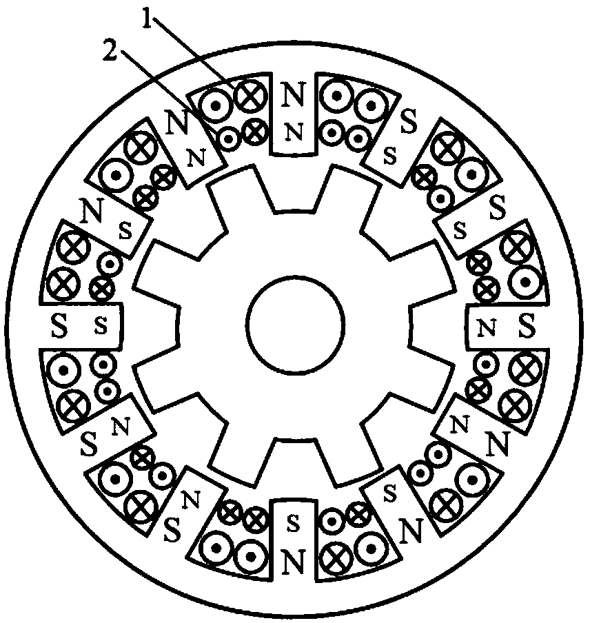
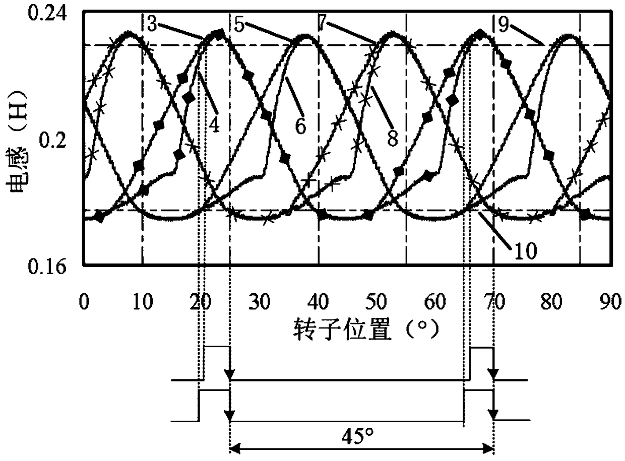
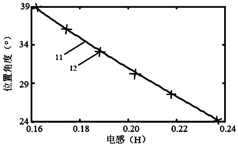
[0043] The invention designs a method for estimating the rotor position of a switched reluctance motor, which has the function of phase shift compensation and considers the influence of the saturation of the main magnetic circuit on the inductance of the detection coil. The problem of the influence of the strong nonlinearity of the detection coil inductance on the position estimation is solved, and at the same time, the problem of the influence of the phase shift caused by the analog filtering on the position estimation accuracy during the indirect acquisition of the detection coil inductance information is solved.

[0044] The present invention designs a method for estimating the rotor position of a switched reluctance motor. Phase windings and A, B, and C three-phase detection coils are wound on the stator of the switch...


PUM


Abstract

The invention relates to a method for estimate that rotor position of switched reluctance motor. Based on the inductance characteristics of the saturated main magnetic circuit, A rotor position estimation strategy with saturated nonlinear inductance interval avoiding detection coil is proposed, Considering the problem of phase shift caused by analog filtering in the process of indirect acquisitionof inductance information of detection coil, a phase shift compensation algorithm is designed according to the phase shift theory to eliminate the position estimation error and further improve the position estimation accuracy. Through the above design, the detection coil technology can meet the requirements of dynamic operation under various load conditions, and can also achieve accurate positioning of the static initial position, to achieve frequent non-reverse starting of the motor. Therefore, it is helpful for its application in aerospace starter generators, electric vehicle drive motors and other applications where the reliability requirements are extremely high and the operating conditions are relatively harsh.

Description

technical field [0001] The invention relates to a method for estimating the rotor position of a switched reluctance motor, belonging to the technical field of motor detection. Background technique [0002] The switched reluctance motor has the characteristics of simple and sturdy structure, suitable for high-speed, high-temperature operation, and strong fault tolerance. Rotor position detection or estimation is one of the most critical links in the switched reluctance motor system. Traditional rotor position sensors are susceptible to high temperature, high speed, dust and other working conditions or environmental factors, and their reliability and tolerance to harsh environments are relatively low. To solve the problems of sensors, no position sensor technology and indirect position detection technology are extremely important. The position sensorless technology needs to use the motor inductance or flux linkage characteristics. The positionless algorithm and the motor con...

Claims


Application Information

Patent Timeline
Patent Type & Authority Applications(China)
IPC IPC(8): H02P6/185
CPCH02P6/185
Inventor 蔡骏向程徐放刘泽远赵兴强贾红云
Owner NANJING UNIV OF INFORMATION SCI & TECH
Why Eureka
Eureka Blog
Learn More