
Automatic nailing device

An automatic and clamping device technology, applied in auxiliary devices, auxiliary welding equipment, welding/cutting auxiliary equipment, etc., can solve the problems of low nailing efficiency, difficult operation, and low processing quality

Active Publication Date: 2018-12-21
广州创研智能科技有限公司
View PDF5 Cites 2 Cited by
  • Summary
  • Abstract
  • Description
  • Claims
  • Application Information

AI Technical Summary

Problems solved by technology

[0004] The present invention aims to provide an automatic nailing device to improve the problems of low nailing efficiency, difficult operation and low processing quality in the prior art

Method used


Image

  • Automatic nailing device
  • Automatic nailing device
  • Automatic nailing device

Examples


Embodiment 1

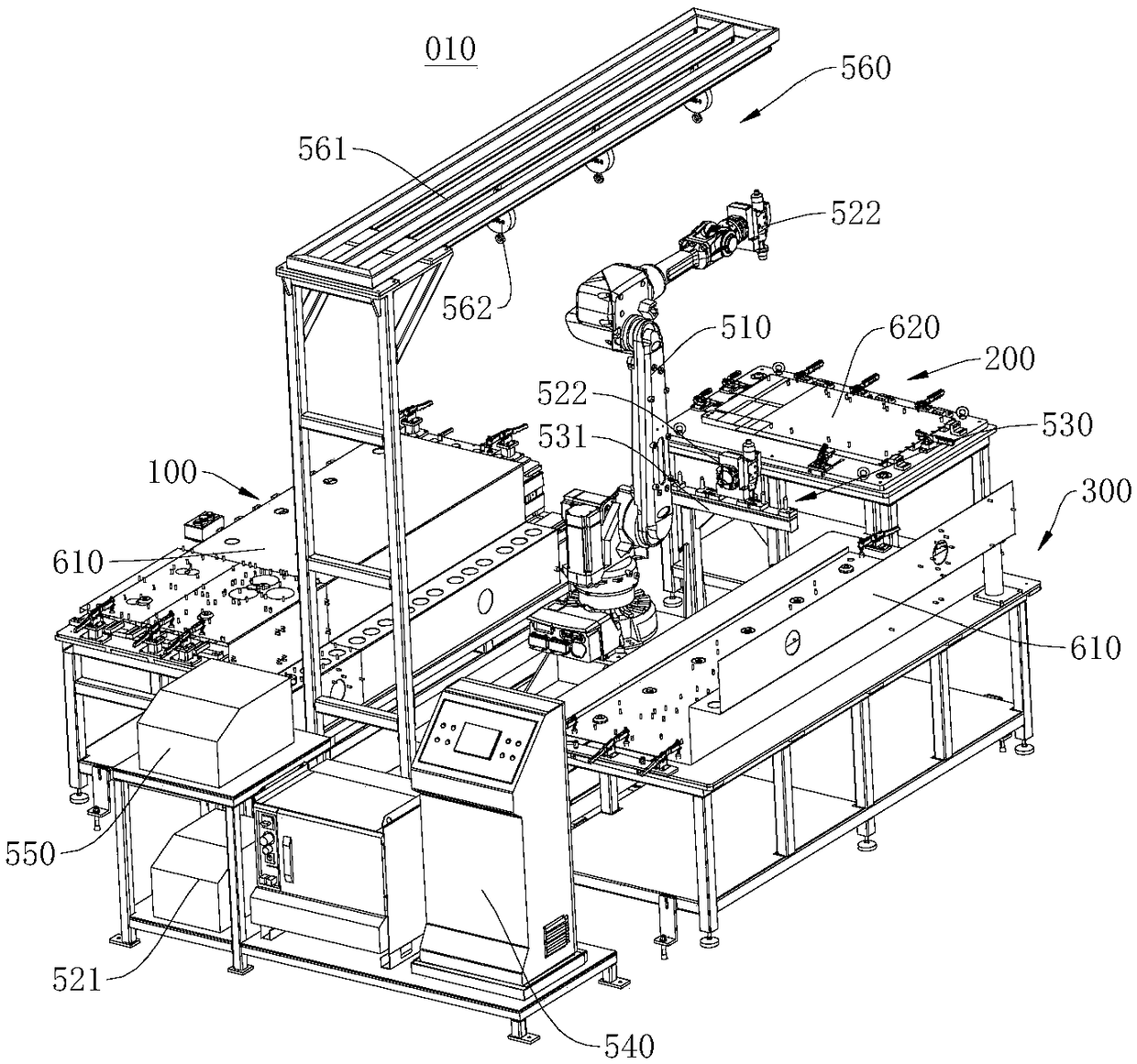
[0043] figure 1 A schematic diagram of the overall structure of the automatic nailing device 010 provided in this embodiment. Please refer to figure 1, the present embodiment provides an automatic nailing device 010 , which includes an operating table 540 , a nail feeding machine 550 , a nailing robot 510 , and a first clamping mechanism 100 and a second clamping mechanism 200 . The first clamping mechanism 100 is used to fix the first workpiece 610 to be nailed, and the second clamping mechanism 200 is used to fix the second workpiece 620 to be nailed. The nailing robot 510 is fixedly connected with a nailing mechanism, and the nail feeding machine 550 is used to deliver screws to the nailing mechanism. Perform nailing operations in different positions. Moreover, the nail feeder 550, the nailing robot 510, and the nailing mechanism are all connected to the control console 540. Under the control of the console 540, the nail feeder 550 can automatically deliver the screws to...


PUM


Abstract

The invention relates to the technical field of mechanical processing, and aims to provide an automatic nailing device. The automatic nailing device provided by the invention comprises an operating table, a nail feeding machine, a nailing robot, a first clamping mechanism, and a second clamping mechanism. The first clamping mechanism is used for fixing a first workpiece to be nailed, and the second clamping mechanism is used for fixing a second workpiece to be nailed. The nailing robot is fixedly connected with a nailing mechanism. The nail feeding machine is used for feeding screws to the nailing mechanism. The nailing mechanism moves under the driving of the nailing robot, and can perform nailing operations at different positions on the first workpiece and the second workpiece. In addition, the nail feeding machine, the nailing robot, and the nailing mechanism are all connected with the operating table, and under the control of the operating table, the nailing operations are automatically performed, the nailing efficiency is high, the labor intensity of workers is low, and the nailing quality can be guaranteed.

Description

technical field [0001] The invention relates to the technical field of mechanical processing, in particular to an automatic nailing device. Background technique [0002] In the field of mechanical processing, it is often necessary to press the screw on the workpiece. The existing nailing operation is often carried out by welding, and the metal at the contact part of the screw and the workpiece is rapidly self-fused through instantaneous discharge to achieve welding. Effect. [0003] At present, a hand-held welding torch is usually used to complete the welding work, and the torch head of the hand-held welding torch is provided with a sleeve for clamping welding nails. However, with the above-mentioned method, manual operation is completely used during welding, which is inefficient and difficult to perform manual operation, and it is difficult to guarantee welding efficiency and welding quality. Contents of the invention [0004] The present invention aims to provide an au...

Claims


Application Information

Patent Timeline
Patent Type & Authority Applications(China)
IPC IPC(8): B23K37/00
CPCB23K37/00
Inventor 张人斌李国栋张强
Owner 广州创研智能科技有限公司
Learn More