
Sedimentation tank desilting device

A technology of dredging device and sedimentation tank, which is applied in the direction of sedimentation separation, feeding/discharging device of sedimentation tank, chemical instruments and methods, etc. It can solve the problems of many turnover sedimentation tanks, unsolved dredging problems, complicated process, etc.

Active Publication Date: 2018-12-21
崔璨
View PDF9 Cites 7 Cited by
  • Summary
  • Abstract
  • Description
  • Claims
  • Application Information

AI Technical Summary

Problems solved by technology

In the existing sewage treatment process, there is generally a sedimentation process. For a large amount of sediment in the sewage, a sedimentation tank is often used to settle the sediment. The sludge after sedimentation has a large water content and the sludge is fluid, which is troublesome to deal with. , in the state where clean water and silt cannot be separated, the method of placing a suction pump directly at the bottom of the pool is often used, which is easy to mix when absorbing silt; or the method of removing clean water first and then dredging, but more sedimentation tanks need to be turned over, and the water conduction capacity Huge, leading to unsatisfactory dredging effect; there are innovative explorations in dredging in the national patent library, such as invention patent: a sewage treatment equipment that facilitates cleaning of impurities (application number 201810498595.6), utility model patent: a municipal sewage The treatment device (application number 201721423187.1) adopts the method of sedimentation, drainage and desilting in multiple ponds. Although it can play the role of desilting sedimented sewage, the investment in the facilities is too large, the process is complicated, the cleaning is cumbersome, and the effect is not obvious. The most fundamental The problem is that the problem of dredging in the coexistence of clean water and silt in the pool is not solved, which is not conducive to the healthy operation of sewage treatment. At present, there is no good way to solve the above problems

Method used


Image

  • Sedimentation tank desilting device
  • Sedimentation tank desilting device
  • Sedimentation tank desilting device

Examples


Embodiment Construction

[0025] The present invention includes a sedimentation tank 1 and a silt discharge mechanism 2 .

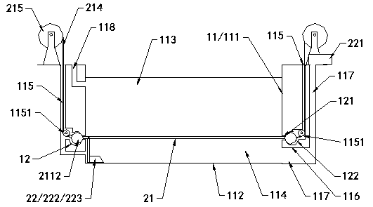
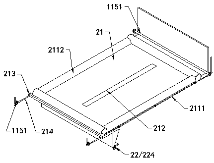
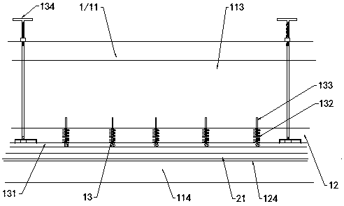
[0026] Such as figure 1 As shown, the sedimentation tank 1 is rectangular, the bottom 112 of the pool body 11 is surrounded by a vertical wall 111, and the upper end of the pool body is provided with a sewage inlet pipe 118, which is used to introduce sewage to be treated. After the sewage is treated, it settles in the pool. Divided into a water purification layer 113 and a sedimentation layer 114, the vertical wall between the water purification layer and the sedimentation layer is provided with a horizontal groove sandwiching channel 12, the grooves in the front end and the vertical walls on both sides are connected at an angle, and the rear The lower end of the side vertical wall is provided with a partition 116, and the upper surface of the partition is flush with the lower plate 124 of the grooves on both sides. Annular groove clamping channel.

[0027] The upper end of the...


PUM


Abstract

The invention discloses a sedimentation tank desilting device. Annular groove passageways are formed in the lower section of a sedimentation tank; an isolating cloth membrane moves along the groove passageways in the two sides of a tank body after being drawn and can cover a silting layer at the bottom of the tank or wind one end of the tank body; clamping pieces on the periphery of the isolatingcloth membrane are clamped and sealed with the groove passageways in the corresponding positions; a desilting piece is arranged on the silting layer at the bottom of the tank. The sedimentation tank desilting device is different from a conventional desilting mode; the isolating cloth membrane can be drawn and can cover at the upper end of the silting layer in the state that stagnant water and sediment silt in the tank coexist; the periphery of the isolating cloth membrane and the groove passageways in the tank body are sealed and clamped to separate clean water from the silt in the tank body;flow state silt is scraped away or pumped away by a pump after the desilting piece stirs or flushes in the silting layer; when desilting is performed, the stagnant water and the silt are prevented from being mixed; water pressure does not change; work efficiency is reduced; the investment is low; a new desilting way is created.

Description

technical field [0001] The invention relates to the field of sewage treatment for environmental governance, in particular to a desilting device for a sedimentation tank. Background technique [0002] With the advancement of science and technology and the development of society, urban and rural living and production water will produce a large amount of sewage every day, and improving water environmental pollution has become a difficult problem that needs to be solved urgently in my country's environmental problems. In the existing sewage treatment process, there is generally a sedimentation process. For a large amount of sediment in the sewage, a sedimentation tank is often used to settle the sediment. The sludge after sedimentation has a large water content and the sludge is fluid, which is troublesome to deal with. , in the state where clean water and silt cannot be separated, the method of placing a suction pump directly at the bottom of the pool is often used, which is ea...

Claims


Application Information

Patent Timeline
Patent Type & Authority Applications(China)
IPC IPC(8): B01D21/24
CPCB01D21/245B01D21/2472
Inventor 张霰李冬崔建国
Owner 崔璨
Learn More