
A hot stamping machine

A hot stamping machine and rack technology, applied in the field of hot stamping machines, can solve problems such as unfavorable work efficiency, lower utilization rate of foil paper, and inability of hot stamping machines to perform hot stamping operations, so as to achieve the effect of improving the flexibility of use and improving the utilization rate

Active Publication Date: 2020-07-14
温州欧宏机械有限公司
View PDF6 Cites 0 Cited by
  • Summary
  • Abstract
  • Description
  • Claims
  • Application Information

AI Technical Summary

Problems solved by technology

[0003] The existing bronzing machine includes a fixed mold fixed on the frame, a movable mold slidably connected to the frame, a driving part for driving the movable mold, and a foil feeding device capable of conveying foil, wherein The fixed mold, movable mold, and foil feeding device are all set up with the specifications of the hot stamping machine, and can only be used for hot stamping operations on products to be printed within a certain range of specifications, and the hot stamping machine cannot perform hot stamping on products to be printed that are too large operation, but the product to be printed is too small, and the foil paper without design text or pattern area will not be used after one hot stamping operation, which greatly reduces the utilization rate of the foil paper
And when a product to be printed needs to be hot stamped in different positions or colors, it is necessary to replace the hot stamping machine several times, and repeated replacement positions not only reduce the accuracy of the hot stamping position, but also increase the labor load of the workers. Conducive to improving work efficiency

Method used


Image

  • A hot stamping machine
  • A hot stamping machine
  • A hot stamping machine

Examples


Embodiment Construction

[0032] The present invention will be described in further detail below in conjunction with the accompanying drawings and embodiments. Wherein the same components are denoted by the same reference numerals. It should be noted that the words "front", "rear", "left", "right", "upper" and "lower" used in the following description refer to the directions in the drawings, and the words "bottom" and "top "Face", "inner" and "outer" refer to directions toward or away from, respectively, the geometric center of a particular component.

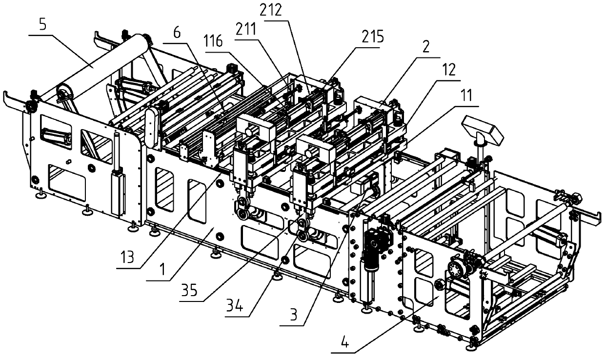
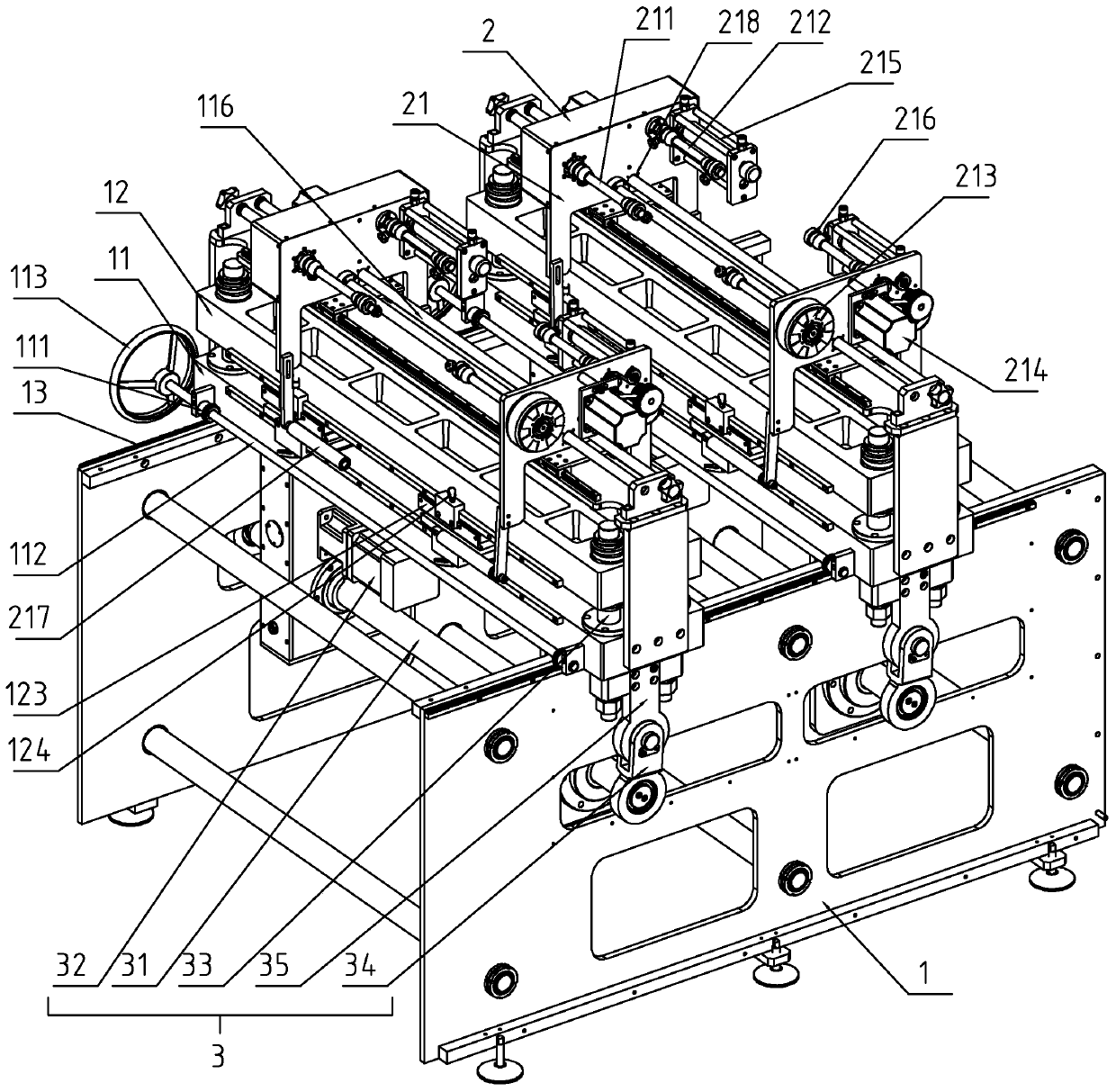
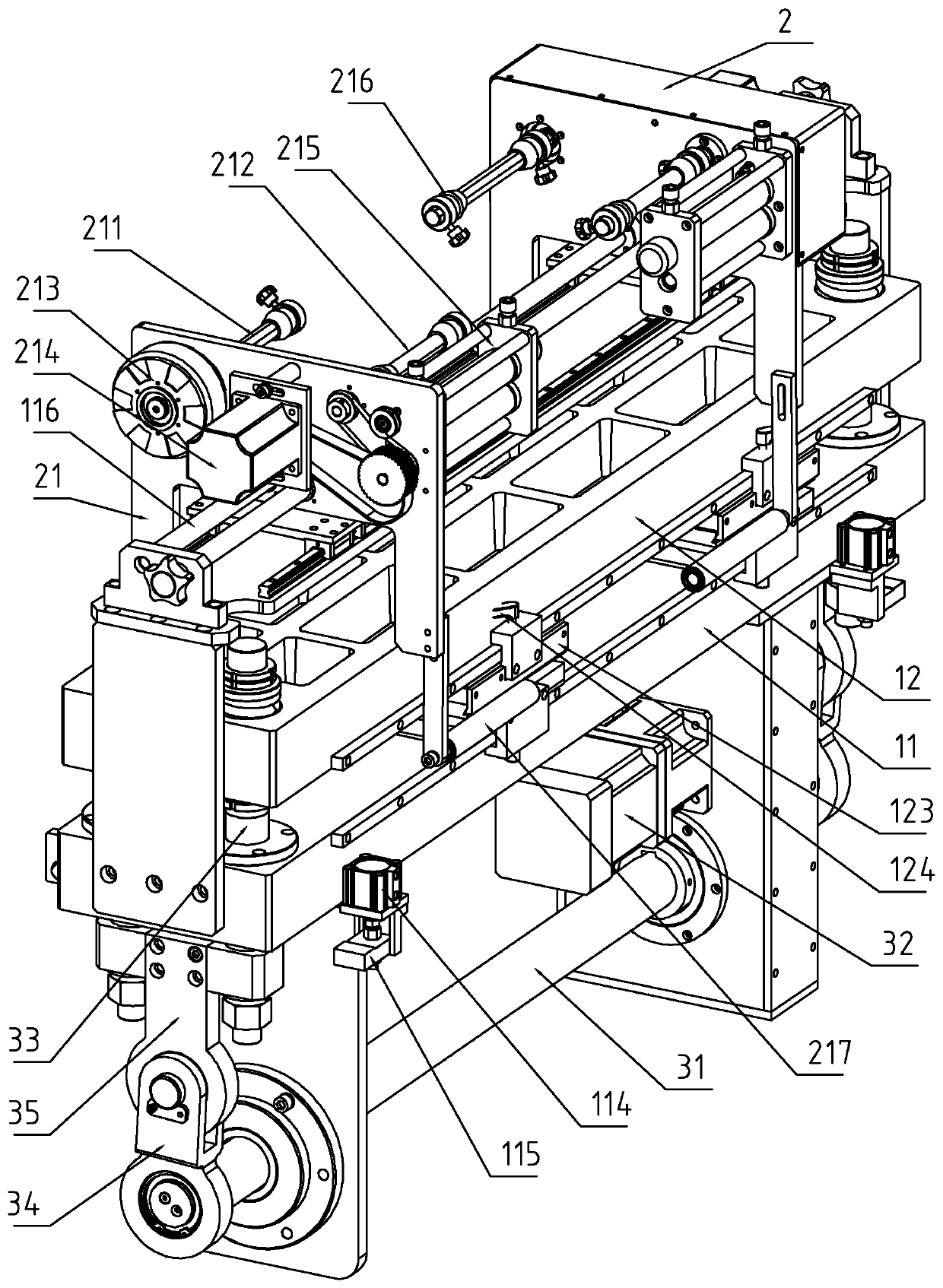
[0033] refer to Figure 1-9 As shown, a hot stamping machine includes a feeding device 4 for releasing the coil material to be printed, a hot stamping device for hot stamping the coil material to be printed, and a receiving device 5 for collecting the coil material to be printed, The feeding device 4 is located at the feeding end of the bronzing device, and the receiving device 5 is located at the discharging end of the bronzing device, and the coil m...


PUM


Abstract

The invention discloses a bronzing machine. According to the technical scheme, the bronzing machine comprises a feeding device, a bronzing device and a collecting device. The bronzing device comprisesa rack, multiple fixed dies, movable dies, foil paper feeding devices and drive parts. The fixed dies are all slidingly connected with the rack, the rack is provided with ratchet bars, and the fixeddies are rotationally connected with ratchet gears. The number of the foil paper feeding devices, the number of the movable dies and the number of the drive parts are all kept consistent with the number of the fixed dies, and a controller and a detection probe are further arranged on the rack. Each foil paper feeding device comprises multiple feeding mounting frames, the fixed dies are rotationally connected with drive screw shafts, the number of the drive screw shafts is kept consistent with the number of the feeding mounting frames, and one drive screw shaft is in screw joint with one feeding mounting frame. The bronzing machine is high in use flexibility, the utilization rate of foil paper can be effectively increased, re-positioning is not needed when hot stamping operation in different positions or different colors needs to be carried out, and the accuracy and the precision of hot stamping positions can be improved.

Description

technical field [0001] The present invention relates to the technical field of printing equipment, more specifically, it relates to a bronzing machine. Background technique [0002] Hot stamping, also known as "hot stamping". A printing decoration process. Heat the hot stamping font, apply foil, and emboss golden characters or patterns on the printed matter. With the rapid development of hot stamping foil and packaging industry, the application of hot stamping is becoming more and more extensive. [0003] The existing bronzing machine includes a fixed mold fixed on the frame, a movable mold slidably connected to the frame, a driving part for driving the movable mold, and a foil feeding device capable of conveying foil, wherein The fixed mold, movable mold, and foil feeding device are all set up with the specifications of the hot stamping machine, and can only be used for hot stamping operations on products to be printed within a certain range of specifications, and the ho...

Claims


Application Information

Patent Timeline
Patent Type & Authority Patents(China)
IPC IPC(8): B41F19/06
CPCB41F19/068B41P2219/13B41P2219/42
Inventor 涂其德
Owner 温州欧宏机械有限公司
Learn More