A lifting air suspension system and automobile

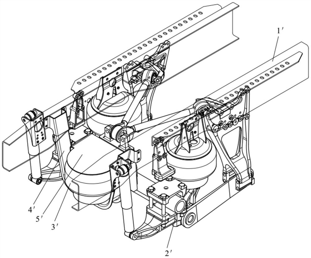
An air suspension and automobile technology, applied in the field of vehicles, can solve the problems of unbalanced force on the frame 1', increased manufacturing cost, stress concentration of the frame 1', etc., so as to save installation space, improve versatility, and improve comfort sexual effect

Active Publication Date: 2020-12-22
WEICHAI POWER CO LTD
View PDF12 Cites 0 Cited by
  • Summary
  • Abstract
  • Description
  • Claims
  • Application Information

AI Technical Summary

Problems solved by technology

[0004] First of all, when applied on the electric axle 2', since the lifting airbag 3' is arranged in the middle of the electric drive axle 2', a lot of central space is wasted
Especially for lifting the middle axle, the middle part needs the transmission shaft to pass through, and the lifting airbag 3' occupies the middle position, which makes the installation and assembly of the transmission shaft difficult, so this method has certain limitations
[0005] Secondly, in order to ensure a good lifting and lowering effect on the axle 2', generally the size of the lifting airbag 3' is relatively large, so that the size of the upper bracket 5' and the lower bracket 4' that are fixed thereon are also larger, thereby increasing the manufacturing cost
[0006] Again, although a larger lifting airbag 3' is arranged in the middle of the vehicle frame 1', there is still a situation where the vehicle frame 1' is unbalanced in force, which makes the vehicle frame 1' prone to stress concentration

Method used


Image

  • A lifting air suspension system and automobile
  • A lifting air suspension system and automobile
  • A lifting air suspension system and automobile

Examples


Embodiment Construction

[0034] The technical solutions of the present invention will be further described below in conjunction with the accompanying drawings and through specific implementation methods.

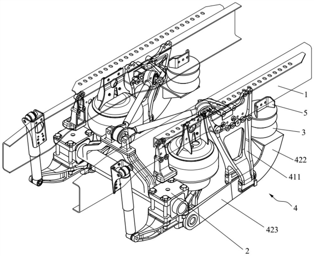
[0035] This embodiment provides a lifting air suspension system, such as figure 2 As shown, the lifting air suspension system includes a vehicle frame 1, an axle 2, two lifting airbags 3 and two transmission mechanisms 4, and the two lifting airbags 3 are respectively arranged on both sides of the vehicle frame 1, wherein each transmission mechanism One end of 4 is connected to a lifting airbag 3, and the other end is connected to one side of the axle 2. At the same time, the lifting airbag 3 is arranged between the vehicle frame 1 and the transmission mechanism 4, and the lifting of the vehicle axle 2 can be realized through the transmission mechanism 4. and landing.

[0036] One end of each transmission mechanism 4 is connected to a lifting airbag 3, and the other end is connected to one side of...


PUM


Abstract

The invention belongs to the technical field of vehicles, and discloses a lifting air suspension system and an automobile. The lifting air suspension system comprises an automobile frame, an axle, twolifting air bags and two transmission mechanisms, the two lifting air bags are arranged at the two sides of the automobile frame, wherein one end of each transmission mechanism is connected to the corresponding lifting air bag, the other end of the corresponding transmission mechanism is connected to one side of the axle, the lifting air bags are arranged between the automobile frame and the transmission mechanisms, and the axle can ascend and descend through the transmission mechanisms. The lifting air suspension system has the advantages that the two lifting air bags are arranged at the twosides of the automobile frame respectively, middle installation space is saved, for lifting an intermediate axle, space is provided for the installation and assembly of a transmission shaft needing to pass through the middle, thereby improving the universality; the stress concentration is reduced, and the effect of the force balance of the automobile frame is enhanced.

Description

technical field [0001] The invention relates to the technical field of vehicles, in particular to a lifting air suspension system and an automobile. Background technique [0002] The lifting air suspension system is an air suspension structure that can lift and lower the axle through air springs. [0003] Such as figure 1 As shown, in the prior art, the lifting airbag 3' is arranged in the middle of the vehicle frame 1', and the upper end of the lifting airbag 3' is connected to the axle 2' through a larger upper bracket 5', and the lifting airbag 3' The lower end is carried by the lower bracket 4' and connected with the vehicle frame 1'. There are following defects in this way: [0004] First of all, when applied on the electric vehicle axle 2', because the lifting airbag 3' is arranged in the middle position of the electric drive vehicle axle 2', a large amount of central space is wasted. Especially for lifting the middle axle, the middle part needs the transmission sh...

Claims


Application Information

Patent Timeline
Patent Type & Authority Patents(China)
IPC IPC(8): B60G11/27B60G11/28B60G17/00
CPCB60G11/27B60G11/28B60G17/00
Inventor 庞向东常勇申振华谢欢林安
Owner WEICHAI POWER CO LTD
Why Eureka
Try Eureka