Temporary shield for communication equipment
A technology for temporary protection and communication equipment, which is applied in the direction of casings/cabinets/drawer components, etc., which can solve the problems of difficulty in meeting the temporary protection requirements of communication equipment of different sizes, unfavorable protection of communication equipment, and affecting construction progress, etc., to achieve convenience Adjust the hook, avoid accidental damage, and avoid excessive interference
- Summary
- Abstract
- Description
- Claims
- Application Information
AI Technical Summary
Problems solved by technology
Method used
Image
Examples
Embodiment 1
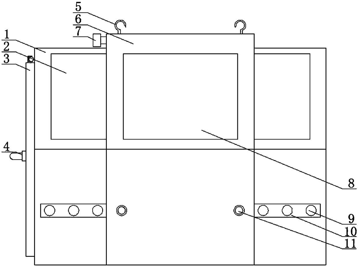
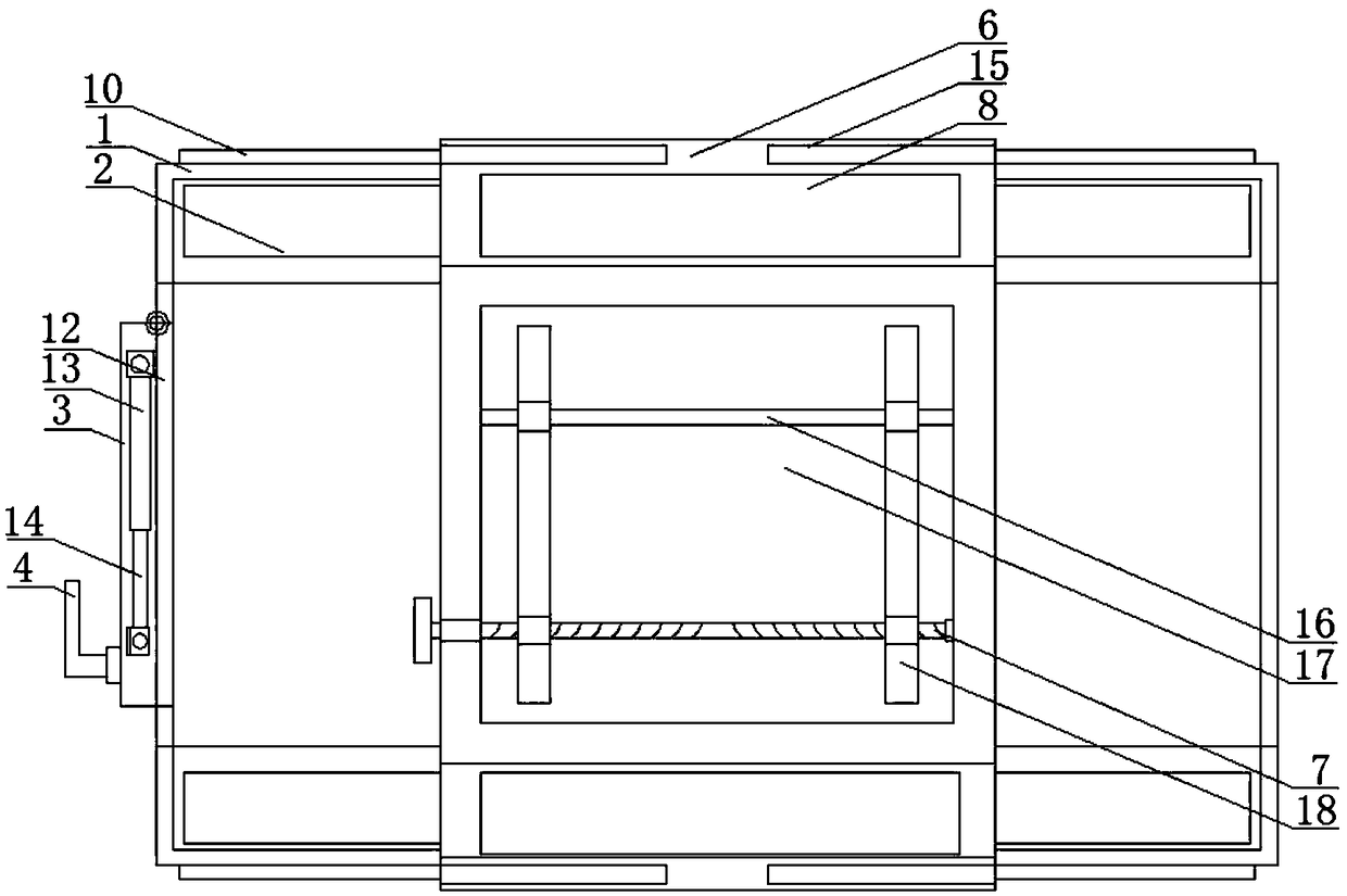
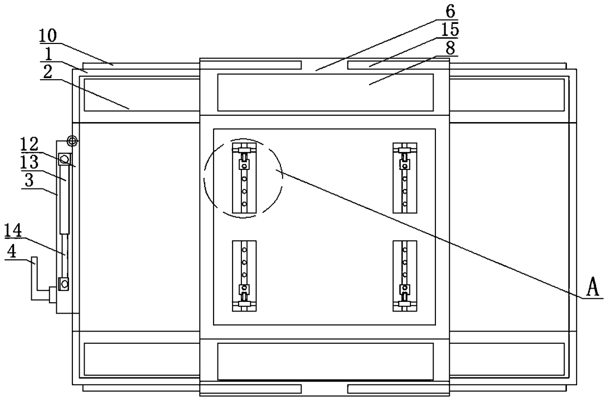
[0027] refer to figure 1 , 2 3, a temporary protective cover for communication equipment, comprising a second U-shaped plate 6, the top in the second U-shaped plate 6 is provided with a groove 17, and the opposite side walls in the groove 17 are jointly fixed with a cross bar 16, Two moving plates 18 are slidably sleeved on the cross bar 16, which facilitates the movement of the two moving plates 18 and limits the moving range of the moving plates 18;
[0028] A threaded rod 7 is threadedly sleeved on the two moving plates 18, and one end of the threaded rod 7 is rotatably connected to one end sidewall of the groove 17, and one end of the threaded rod 7 extends through the groove 17 to the second U-shaped plate. 6, the two ends of the threaded rod 7 are respectively provided with a forward thread and a reverse thread, one of the moving plates 18 is threadedly sleeved on the end of the threaded rod 7 with a forward thread, and the other moving plate 18 is threadedly sleeved. ...
Embodiment 2
[0032] refer to figure 1 , 2 , 3, 5, a temporary protective cover for communication equipment, including a second U-shaped plate 6, the top in the second U-shaped plate 6 is provided with a groove 17, and the opposite side walls in the groove 17 are jointly fixed with a cross bar 16. Two moving plates 18 are slidably sleeved on the cross bar 16 to facilitate the movement of the two moving plates 18 and limit the movement range of the moving plates 18;
[0033] A threaded rod 7 is threadedly sleeved on the two moving plates 18, and one end of the threaded rod 7 is rotatably connected to one end sidewall of the groove 17, and one end of the threaded rod 7 extends through the groove 17 to the second U-shaped plate. 6, the two ends of the threaded rod 7 are respectively provided with a forward thread and a reverse thread, one of the moving plates 18 is threadedly sleeved on the end of the threaded rod 7 with a forward thread, and the other moving plate 18 is threadedly sleeved. ...
Embodiment 3
[0039] refer to figure 1 , 2 , 3, 4, a temporary protective cover for communication equipment, comprising a second U-shaped plate 6, the top in the second U-shaped plate 6 is provided with a groove 17, and the opposite side walls in the groove 17 are jointly fixed with a cross bar 16. Two moving plates 18 are slidably sleeved on the cross bar 16 to facilitate the movement of the two moving plates 18 and limit the movement range of the moving plates 18;
[0040] A threaded rod 7 is threadedly sleeved on the two moving plates 18, and one end of the threaded rod 7 is rotatably connected to one end sidewall of the groove 17, and one end of the threaded rod 7 extends through the groove 17 to the second U-shaped plate. 6, the two ends of the threaded rod 7 are respectively provided with a forward thread and a reverse thread, one of the moving plates 18 is threadedly sleeved on the end of the threaded rod 7 with a forward thread, and the other moving plate 18 is threadedly sleeved. ...
PUM
 Abstract
Description
Claims
Application Information
 - R&D
- Intellectual Property
- Life Sciences
- Materials
- Tech Scout
- Unparalleled Data Quality
- Higher Quality Content
- 60% Fewer Hallucinations
Browse by: Latest US Patents, China's latest patents, Technical Efficacy Thesaurus, Application Domain, Technology Topic, Popular Technical Reports.
© 2025 PatSnap. All rights reserved.Legal|Privacy policy|Modern Slavery Act Transparency Statement|Sitemap|About US| Contact US: help@patsnap.com


