High-efficiency isolating and sealing device for optical cable

A sealing device and optical cable technology, applied in the directions of light guides, optics, optical components, etc., can solve the problems of poor sealing performance and inconvenience, and achieve the effects of improved sealing performance, firm and reliable fixing, and a wide range of effects.

Inactive Publication Date: 2018-11-23
胡肖平
View PDF0 Cites 4 Cited by
  • Summary
  • Abstract
  • Description
  • Claims
  • Application Information

AI Technical Summary

Problems solved by technology

Most of the existing sealing structures for the U-shaped part of the optical cable use heat shrinkable seals or conventional mechanical extrusion seals. Although heat shrinkable seals have relatively stable sealing performance, they need to carry heating equipment during construction, which brings inconvenience to field construction; while conventional Mechanical extrusion sealing, through an integral elastic sealing part, squeezes and seals the two branches of the U-shaped part of the optical cable at the same time, and the sealing performance is poor

Method used


Image

  • High-efficiency isolating and sealing device for optical cable
  • High-efficiency isolating and sealing device for optical cable
  • High-efficiency isolating and sealing device for optical cable

Examples


Embodiment 1

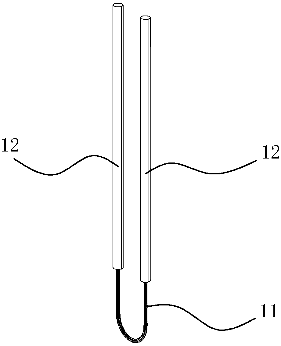
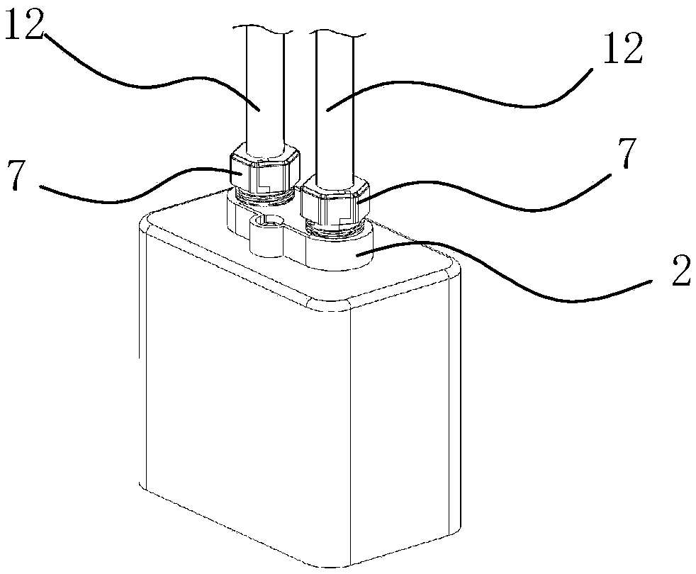
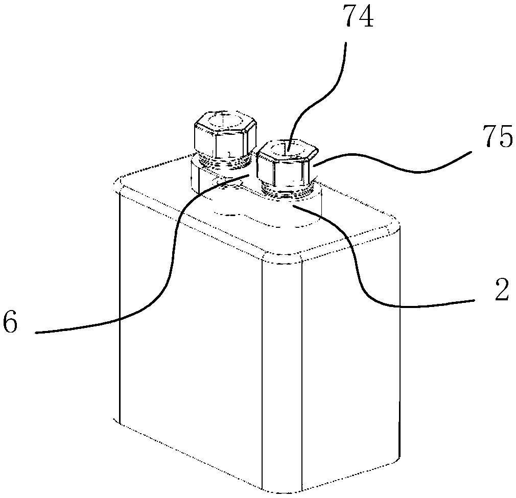
[0038] see Figure 1-Figure 9 , The high-efficiency isolation and sealing device for optical cables in this embodiment includes a sealing body 2 , a flexible sealing ring 42 , an extrusion ring 5 , an isolator 6 , a screw locking member 7 , a flexible limiting plate 41 , and a spacer 3 .

[0039] The extrusion ring 5 is composed of two semicircular extrusion petals 51 .

[0040] The sealing body 2 is provided with a sealing cavity 21 through which the U-shaped end 11 of the optical cable passes through.

[0041] The inner end of the sealing cavity 21 has a flexible limiting plate 41 against the flexible sealing ring 42, and the inner end wall of the sealing cavity 21 is integrally extended with a limiting edge 23 for resisting the flexible limiting plate 41, limiting The middle part of the bit edge 23 is provided with a spacer groove 24, and the spacer 3 is snapped into the spacer groove 24, and the side surface of the spacer 3 is flush with the side surface of the spacer edg...

Embodiment 2

[0054] see Figure 11-Figure 15 The high-efficiency isolation and sealing device for optical cables of this embodiment is basically the same as that of Embodiment 1, the difference being that: both the spacer 6 and the sealing body 2 extend outwards with a semicircular extension piece 9, and the outer convex side of the extension piece 9 is provided with Half thread structure 81, the groove 73 of the first locking part 71 and the groove 73 of the second locking part 72 all have a half thread structure 81, the half thread structure 81 of the first locking part 71 and the second The half-thread structure 81 of the locking portion 72 is combined to form the fastening thread section 82 .

[0055] The high-efficiency isolation and sealing device for optical cables in this embodiment can also be provided with two extrusion rings as described in Embodiment 1 (ie, a composite extrusion ring structure) in each sealing channel.


PUM


Abstract

The invention discloses a high-efficiency isolating and sealing device for an optical cable, and the device is characterized in that the device comprises a sealing main body, a flexible sealing ring,an extruding ring, a separator and a screw locking member, wherein the sealing main body is provided with a sealing cavity which is used for the passing of the whole U-shaped end of the optical cable;the separator is inserted into the sealing cavity and fixed with the sealing main body; the two side walls of the separator are respectively buckled with the two side walls of the sealing cavity, thereby forming two independent sealing channels in the sealing cavity. After the whole U-shaped end of the optical cable passes through the sealing cavity, the separator is inserted into the sealing cavity, and two independent sealing channels are obtained for separating and sealing two branches of the U-shaped end of the optical cable, thereby enabling the operation of inserting the U-shaped end ofthe optical cable into a wiring box to be more convenient.

Description

technical field [0001] The invention belongs to the technical field of optical communication equipment, and in particular relates to a high-efficiency isolation and sealing device for optical cables. Background technique [0002] The existing optical cable connection end protection device, also known as optical cable junction box, belongs to the mechanical pressure sealing joint system, and is a connection protection device that provides optical, sealing and mechanical strength continuity between adjacent optical cables. It is mainly suitable for straight-through and branch connections of overhead, pipeline, direct buried and other laying methods of optical cables of various structures. As a commonly used terminal protection device at present, the optical cable connection end protection device has been widely used. When the non-end of the optical cable is connected to the splice box, it is necessary to bend the access part of the optical cable into a U shape, and the U-shape...

Claims


Application Information

Patent Timeline
Patent Type & Authority Applications(China)
IPC IPC(8): G02B6/44
CPCG02B6/4446
Inventor 胡肖平
Owner 胡肖平
Why Eureka
Try Eureka