
Automatic engineering machine special for lifting and hoisting of asphalt tank

A technology for automation engineering and asphalt tanks, applied in cranes, transportation and packaging, load hanging components, etc., can solve the problems of high labor intensity, low work efficiency, poor work flexibility, etc., and achieve the effect of reducing labor intensity and improving efficiency.

Active Publication Date: 2018-11-23
JIANGSU GOLDEN CUBE ENVIRONMENTAL TECH CO LTD
View PDF4 Cites 3 Cited by
  • Summary
  • Abstract
  • Description
  • Claims
  • Application Information

AI Technical Summary

Problems solved by technology

[0003] In order to solve the above-mentioned problems, the present invention provides an automatic construction machine specially used for hoisting and transporting asphalt tanks, which can solve the problem that existing asphalt tanks need to be lifted manually with the help of existing lifting equipment during the lifting process of asphalt tanks. It is necessary to fix the asphalt tank manually with the help of ropes and other tools. The existing lifting equipment is large in size and poor in work flexibility. Manually fixing the asphalt tank with ropes is unstable and cannot guarantee the safety of the asphalt tank during lifting. Potential safety hazard. During the process of lifting the asphalt tank manually, the asphalt tank was not effectively limited and fixed, causing the asphalt tank to sway in the air, threatening the safety of the staff, complex operations, high labor intensity and low work efficiency. It can realize the function of stable lifting of asphalt tanks, without manual operation, there is no potential safety hazard, and it will not threaten the life safety of the staff. It has the advantages of good flexibility, simple operation, low labor intensity and high work efficiency.

Method used


Image

  • Automatic engineering machine special for lifting and hoisting of asphalt tank
  • Automatic engineering machine special for lifting and hoisting of asphalt tank
  • Automatic engineering machine special for lifting and hoisting of asphalt tank

Examples


Embodiment Construction

[0029] In order to make the technical means, creative features, goals and effects achieved by the present invention easy to understand, the present invention will be further described below in conjunction with specific illustrations.

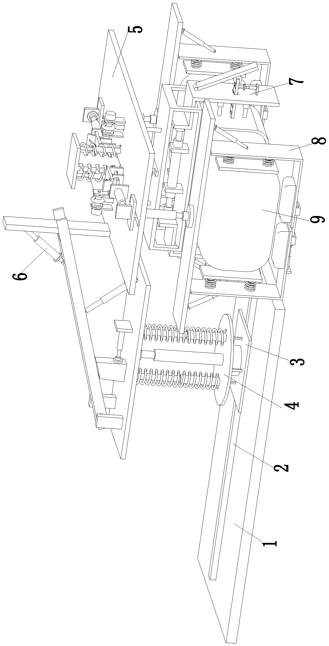
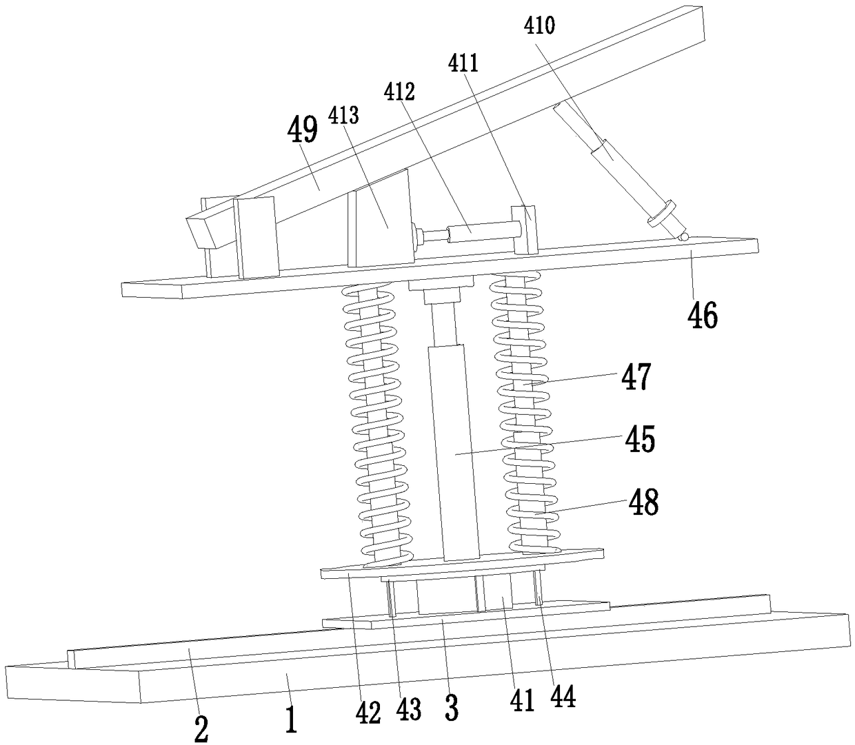
[0030] Such as Figure 1 to Figure 4 As shown in the figure, an automatic construction machine dedicated to lifting and transporting asphalt tanks includes a bottom plate 1, an electric slider 2 is installed on the bottom plate 1, a moving plate 3 is installed on the electric slider 2, and a lifting adjustment is installed on the moving plate 3. Device 4, the front end of the lifting adjustment device 4 is equipped with a fixed installation frame 5 through a pin shaft, the side wall of the fixed installation frame 5 is connected with the top of the fixed adjustment cylinder 6 through a pin shaft, and the bottom end of the fixed adjustment cylinder 6 is installed through a pin shaft On the lifting adjustment device 4, a fixed installation groove ...


PUM


Abstract

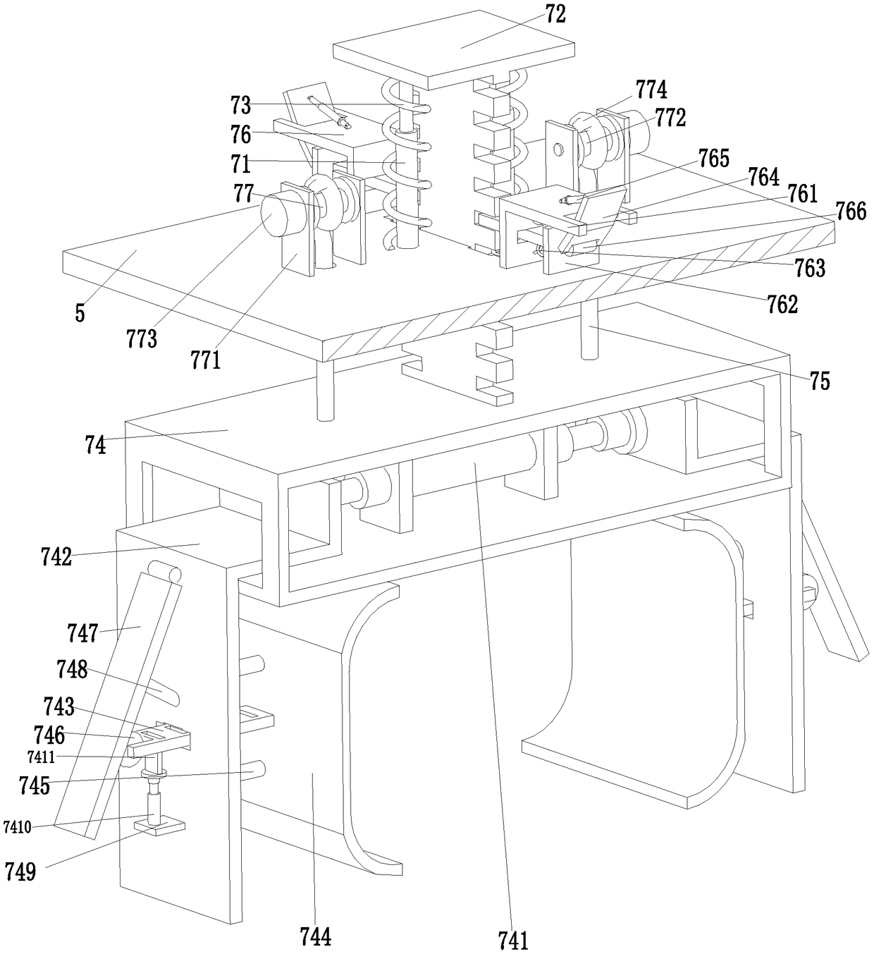
The invention relates to an automatic engineering machine special for lifting and hoisting of an asphalt tank. The automatic engineering machine comprises a bottom plate. An electric sliding block ismounted on the bottom plate and provided with a moving plate. A lifting adjusting device is mounted on the moving plate. A fixed mounting rack is mounted at the front end of the lifting adjusting device through a pin shaft. A fixed mounting groove is arranged in the middle of the fixed mounting rack. A hoisting auxiliary device is mounted in the fixed mounting groove. Fixed feed grooves are arranged on the fixed mounting rack. A hoisting and lifting device is mounted in the fixed feed grooves. According to the automatic engineering machine, the problems that in the hoisting process of an existing asphalt tank, the asphalt tank needs to be hoisted manually by means of existing lifting equipment, the asphalt tank needs to be fixed manually by means of a rope and other tools, the size of theexisting lifting equipment is large, work flexibility is poor, the asphalt tank is fixed unstably manually by means of the rope, the safety of the asphalt tank in the hoisting process cannot be guaranteed, and potential safety hazards exist can be solved.

Description

technical field [0001] The invention relates to the field of lifting and transporting equipment for asphalt tanks, in particular to an automatic engineering machine specially used for lifting and transporting asphalt tanks. Background technique [0002] The asphalt tank and heat transfer oil in the asphalt concrete mixing system are heated and adjusted reasonably, which is the key to reduce the investment cost and improve the economic benefit of the equipment. The asphalt tank is widely used in the field of engineering and construction, but the asphalt tank is bulky during use. It is troublesome. During the transportation and lifting of asphalt tanks, it is necessary to manually lift the asphalt tanks with the help of existing lifting equipment, and manually use tools such as ropes to fix the asphalt tanks. The existing lifting equipment is large in size and difficult to work. The flexibility is poor. Manually fixing the asphalt tanks with ropes is unstable, which cannot gua...

Claims


Application Information

Patent Timeline
IPC IPC(8): B66C23/06B66C23/82B66C1/10B66C1/42B66C13/06
Inventor 潘春燕
Owner JIANGSU GOLDEN CUBE ENVIRONMENTAL TECH CO LTD
Learn More