Beam parts for vehicles
A vehicle and component technology, applied in vehicle components, substructures, superstructures, etc., can solve problems such as the buckling form of beam components that have not been studied in detail, and achieve the effect of increasing buckling load and improving quality efficiency
- Summary
- Abstract
- Description
- Claims
- Application Information
AI Technical Summary
Problems solved by technology
Method used
Image

Examples
no. 1 Embodiment approach
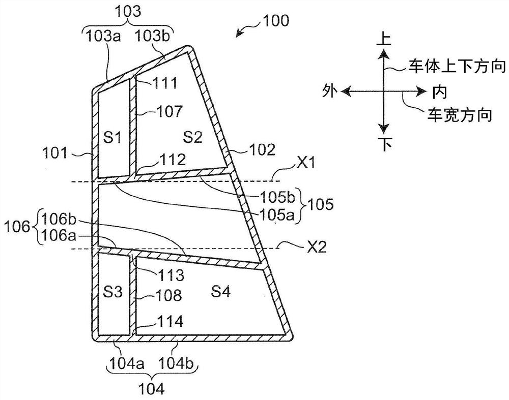
[0057] figure 1 The illustrated beam member 100 constitutes a part of the vehicle body, and is arranged such that its longitudinal direction extends along the vehicle body front-rear direction. In addition, the vehicle body front-rear direction is a direction perpendicular to the vehicle body up-down direction with respect to the vehicle width direction. However, the terms "vehicle body front-rear direction", "vehicle body up-down direction", and "vehicle width direction" in the present invention include not only structures in which the directions are completely perpendicular to each other, but also within the range in which the effects of the present invention can be obtained. , from mutually vertically deviated configurations, it should be understood that it is also included in the present invention.
[0058] figure 1 It is a diagram showing a cross section perpendicular to the longitudinal direction of the beam member 100 (hereinafter simply referred to as the longitudina...
no. 2 Embodiment approach
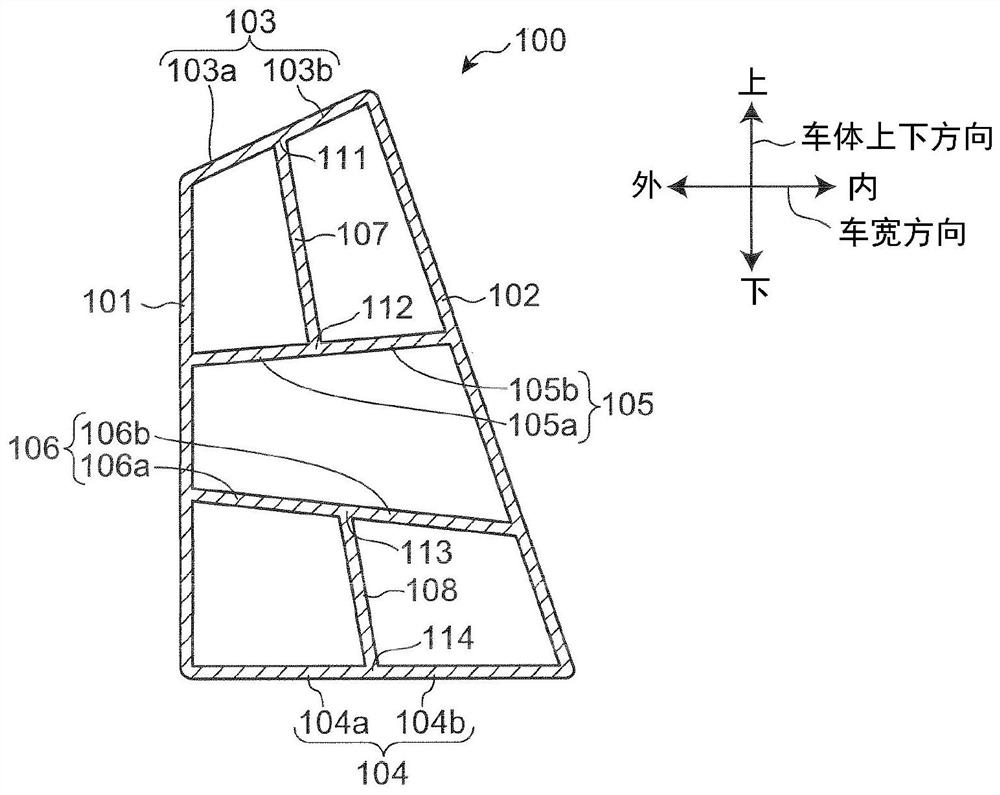
[0089] Figure 6 ~ Figure 8 It is a sectional view showing the beam member 200 according to the second embodiment of the present invention. In the description of the beam member 200 , the same components as those already described in the first embodiment are denoted by the same reference numerals and descriptions thereof are omitted.
[0090] In the beam member 200 , the corner portion 131 on the side forming an acute angle between the first side wall 101 and the upper lateral rib 105 is provided with a larger portion than the portion around the first side wall 101 and the upper lateral rib 105 . The high-strength part of the strength. In addition, the corner portion 132 forming an acute angle between the first side wall 101 and the lower lateral rib 106 is provided with a high-strength portion that is stronger than the portion around the first side wall 101 and the lower lateral rib 106 . Specifically, as Figure 6 ~ Figure 8 As shown, in the corner portions 131 and 132 of...
no. 3 Embodiment approach
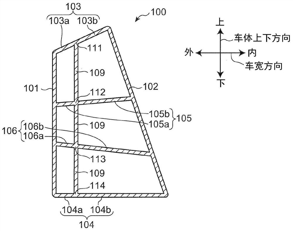
[0093] Figure 9 It is a sectional view showing the beam member 300 according to the third embodiment of the present invention. In the description of the beam member 300 , the same components as those already described in the first and second embodiments are denoted by the same reference numerals and their descriptions are omitted.
[0094] Figure 9 Beam member 300 shown with figure 1The beam member 100 shown is similarly provided with: a first side wall 101, a second side wall 102, an upper wall 103, a lower wall 104, an upper lateral rib 105, a lower lateral rib 106, an upper longitudinal rib 107 and a lower lateral rib. Longitudinal rib 108. Furthermore, in the beam member 300 , reinforcement portions are respectively provided on the outer wall portion 103 a of the upper wall 103 and the outer wall portion 104 a of the lower wall 104 . Specifically, the outer wall portions 103a, 104a of the beam member 300 are respectively provided with thick portions 301, 302 as the r...
PUM
 Abstract
Description
Claims
Application Information
 - R&D
- Intellectual Property
- Life Sciences
- Materials
- Tech Scout
- Unparalleled Data Quality
- Higher Quality Content
- 60% Fewer Hallucinations
Browse by: Latest US Patents, China's latest patents, Technical Efficacy Thesaurus, Application Domain, Technology Topic, Popular Technical Reports.
© 2025 PatSnap. All rights reserved.Legal|Privacy policy|Modern Slavery Act Transparency Statement|Sitemap|About US| Contact US: help@patsnap.com