
Dynamic monitoring method for gas-liquid sealing performance of plunger gas-lift process

A dynamic monitoring and liquid sealing technology, which is applied in the directions of surveying, earthwork drilling and production, wellbore/well components, etc., can solve problems such as lifting failure, reduced fluid discharge, and reduced lifting efficiency, and achieves low monitoring cost and easy Easy to achieve and operate

Active Publication Date: 2018-11-20
XI AN JIAOTONG UNIV
View PDF2 Cites 3 Cited by
  • Summary
  • Abstract
  • Description
  • Claims
  • Application Information

AI Technical Summary

Problems solved by technology

In order to ensure the flexibility of the plunger in the wellbore, there is an annular gap between the plunger and the inner wall of the tubing. The lifted fluid will flow through the annular gap and fall back down, resulting in a decrease in the discharge volume, and the lifting gas will pass through the annular gap. Seams go up, resulting in accelerated attenuation of lifting power, which will lead to a reduction in lifting efficiency or even a lifting failure

Method used


Image

  • Dynamic monitoring method for gas-liquid sealing performance of plunger gas-lift process
  • Dynamic monitoring method for gas-liquid sealing performance of plunger gas-lift process
  • Dynamic monitoring method for gas-liquid sealing performance of plunger gas-lift process

Examples


Embodiment Construction

[0044] The present invention is described in further detail below in conjunction with accompanying drawing:

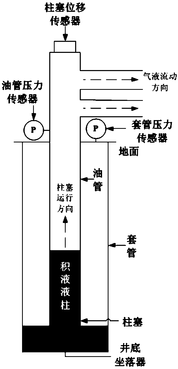
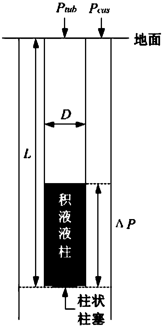
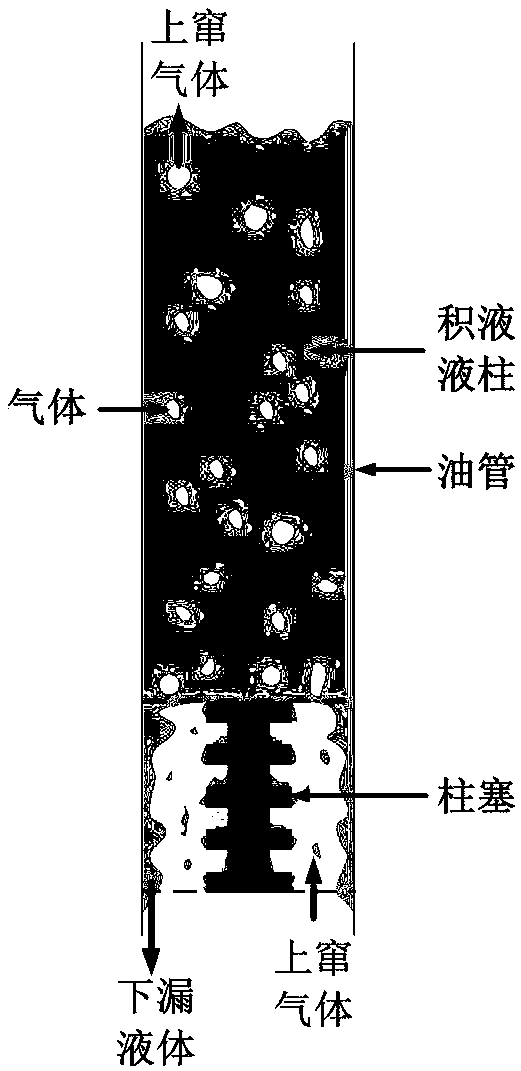
[0045] refer to Figure 1 to Figure 5 , the method for dynamic monitoring of gas-liquid sealing performance in the plunger gas lift process of the present invention comprises the following steps:

[0046] 1) Measure the dynamic pressure of the wellhead tubing through the wellhead pressure sensor and wellhead casing dynamic pressure Then according to the wellhead tubing pressure when the well is opened and lifted and wellhead casing pressure Calculating the mass of liquid column above the plunger when the well is opened and lifted Among them, the mass of the fluid column above the plunger when the well is opened and lifted for:

[0047]

[0048] Among them, L is the depth of the bottom hole seater, g is the acceleration of gravity, and D is the inner diameter of the tubing.

[0049] 2) According to the depth L of the bottom hole seater and the tubing pre...


PUM


Abstract

The invention discloses a dynamic monitoring method for gas-liquid sealing performance of a plunger gas-lift process. The method comprises following steps: 1), dynamic pressure Ptub<[n]> (shown in thedescription) of a wellhead oil pipe and dynamic pressure Pcas<[n]> (shown in the description) of a wellhead casing pipe are measured by a wellhead pressure sensor, and mass ml<[0]> (shown in the description) of an accumulated liquid column above a plunger during well opening and lifting is calculated; 2), driving pressure difference deltaP<[0]> of the plunger at the starting moment is calculated;3), instantaneous displacement Sp<[n]> (shown in the description) of the plunger in the upward lifting process of the plunger is measured by a displacement sensor in the plunger; 4), instantaneous velocity Vp<[n]> (shown in the description) of the plunger during upward lifting is calculated; 5), driving pressure difference deltaP<[n]> of the plunger operating to different positions of a shaft inthe upward lifting process is calculated; 6), gas rate beta<[n]> of the accumulated liquid column above the plunger at different moments in the lifting process is calculated; 7), liquid leakage mass flow Mleak<[n]> (shown in the description) of the upper part of the plunger at different moments in the lifting process is calculated, the gas-liquid sealing performance of the plunger gas-lift processis evaluated, dynamic monitoring for the gas-liquid sealing performance of the plunger gas-lift process is completed, and with the adoption of the method, the gas-liquid sealing performance of the plunger in the lifting process can be accurately monitored in real time.

Description

technical field [0001] The invention belongs to the technical field of plunger gas lift drainage and gas recovery, and relates to a dynamic monitoring method for gas-liquid sealing performance in the plunger gas lift process. Background technique [0002] Plunger gas lift technology, as a more economical method of drainage and gas recovery, does not require too much additional power, and uses formation energy to form a solid interface between the gas and liquid phases in the wellbore through the movable plunger to enhance the gas-liquid seal, thereby Improve drainage and gas production efficiency, increase gas well production, and prolong gas well life. In order to ensure the flexibility of the plunger in the wellbore, there is an annular gap between the plunger and the inner wall of the tubing, and the lifted fluid will flow through the annular gap and fall back down, resulting in a decrease in the discharge volume, and the lifting gas will pass through the annular gap. If...

Claims


Application Information

Patent Timeline
IPC IPC(8): E21B47/00E21B47/008
CPCE21B47/00E21B47/008
Inventor 白博峰赵昆鹏
Owner XI AN JIAOTONG UNIV
Learn More