
Acceptance inspection method and device for indoor coverage antenna

An indoor coverage and antenna technology, which is applied in the field of indoor coverage antenna acceptance, can solve the problems of large acceptance workload, low acceptance accuracy, and the proportion of complex antenna coverage in indoor coverage.

Active Publication Date: 2018-11-13
XIANGYANG BRANCH CHINA MOBILE GRP HUBEI CO LTD +1
View PDF3 Cites 6 Cited by
  • Summary
  • Abstract
  • Description
  • Claims
  • Application Information

AI Technical Summary

Problems solved by technology

Due to the large number of indoor sub-components (such as antennas) and complex coverage (the proportion of concealed antennas in the existing network is relatively high), the acceptance workload for indoor sub-components is very large, and the acceptance is difficult
[0003] The existing inspection method for indoor components mainly adopts the test method of manual on-site random sampling inspection, and the sampling inspection ratio is about 10%.
The existing acceptance method for indoor components has the following technical problems: long acceptance time, unable to fully accept the antenna points in the network access room, insufficient acceptance automation, low acceptance accuracy, etc.
Due to the low acceptance efficiency, it directly affects the indoor signal depth coverage

Method used


Image

  • Acceptance inspection method and device for indoor coverage antenna
  • Acceptance inspection method and device for indoor coverage antenna
  • Acceptance inspection method and device for indoor coverage antenna

Examples


Embodiment Construction

[0030] In order to make the purpose, technical solutions and advantages of the embodiments of the present invention clearer, the technical solutions in the embodiments of the present invention will be clearly and completely described below in conjunction with the drawings in the embodiments of the present invention. Obviously, the described embodiments It is a part of embodiments of the present invention, but not all embodiments. Based on the embodiments of the present invention, all other embodiments obtained by persons of ordinary skill in the art without creative efforts fall within the protection scope of the present invention.

[0031] It should be noted that, in the case of no conflict, the embodiments in the present application and the features in the embodiments can be combined with each other. The present application will be described in detail below with reference to the accompanying drawings and embodiments.

[0032] figure 1 It is a schematic flowchart of an acce...


PUM


Abstract

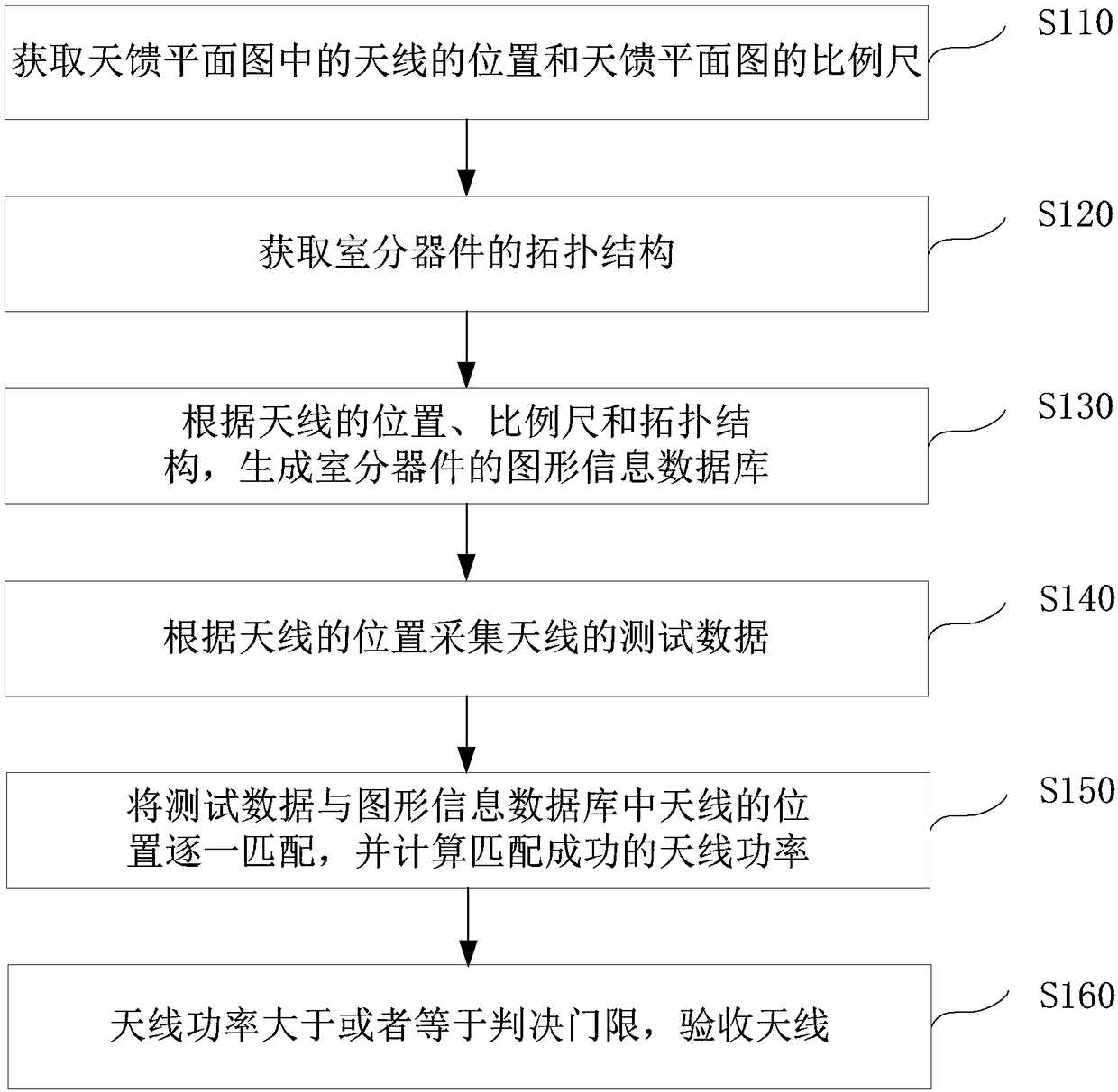
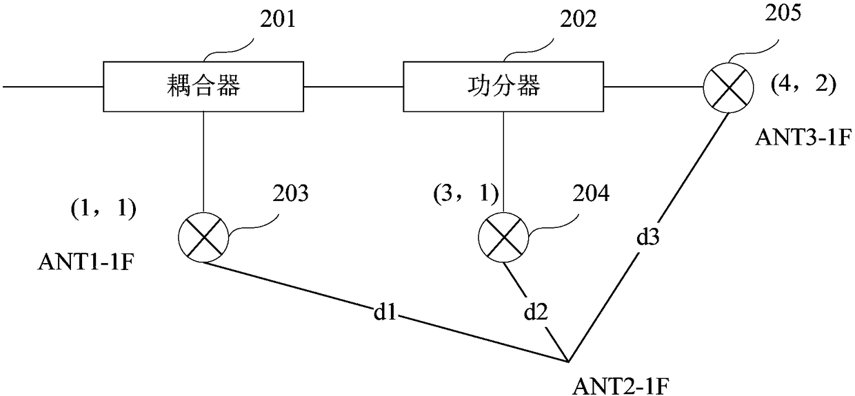
The invention discloses an acceptance inspection method and an acceptance inspection device for an indoor coverage antenna. The method comprises the steps of acquiring antenna positions in an antennafeeder planar graph and a measuring scale of the antenna feeder planar graph; acquiring the topological structures of indoor distributed devices that comprise antennas and superior devices of the antennas; according to the antenna positions, the measuring scale and the topological structures, generating a graphic information database of the indoor distributed devices; according to the antenna positions, collecting test data of the antennas; matching the test data with the antenna positions in the graphic information database one by one, and computing the power of successfully matched antennas;and if the antenna power is more than or equal to a judgment threshold, performing acceptance inspection on the antennas. According to the method and device provided by the embodiment of the invention, the graphic information database of the indoor distributed devices can be generated according to the antenna positions, the measuring scale and the topological structures, and then the test data ismatched with the antenna positions in the graphic information database one by one, so that the power of indoor distributed antenna points accessing the network can be automatically and wholly inspected, and the antenna inspection efficiency is improved.

Description

technical field [0001] The present invention relates to the technical field of wireless communication, in particular to an acceptance method and device for an indoor coverage antenna. Background technique [0002] With the rapid development of wireless communication technology, indoor network signal coverage is gradually developing in the direction of deep coverage. In order to ensure good coverage of indoor network signals, communication companies have built a large number of LTE (Long Term Evolution, Long Term Evolution) indoor distribution systems (referred to as indoor distribution). Due to the large number of indoor sub-components (for example, antennas) and complex coverage (the proportion of concealed installations of antennas in the existing network is high), the acceptance workload for indoor sub-components is very large and the acceptance is difficult. [0003] Existing inspection methods for indoor components mainly adopt manual on-site random sampling inspection...

Claims


Application Information

Patent Timeline
IPC IPC(8): H04B17/10H04B17/17H04B17/21H04B17/318H04W24/04
CPCH04W24/04H04B17/102H04B17/17H04B17/21H04B17/318
Inventor 李素华蔡万强
Owner XIANGYANG BRANCH CHINA MOBILE GRP HUBEI CO LTD
Learn More