Method for calculating induced current of metal sheath of cable under multi-phase and multi-point grounding

A metal sheath, induced current technology, applied in the field of power cables, can solve problems such as the inability to calculate the magnitude of the sheath induced current, and the inability to obtain the distributed sheath induced current.

Active Publication Date: 2018-11-06
SOUTH CHINA UNIV OF TECH
View PDF15 Cites 2 Cited by
  • Summary
  • Abstract
  • Description
  • Claims
  • Application Information

AI Technical Summary

Problems solved by technology

[0004] However, as the cable is laid for a long time, the previous mechanical damage, insect bites and chemical erosion can cause multi-point grounding of the cable metal sheath. When the fault grounding points are in different phases, multi-point multi-phase fault grounding occurs
However, the existing calculation models and calculation methods cannot meet the calculation requirements, that is, the magnitude of the sheath induced current in the fault state cannot be calculated, and the distributed sheath induced current cannot be calculated.

Method used


Image

  • Method for calculating induced current of metal sheath of cable under multi-phase and multi-point grounding
  • Method for calculating induced current of metal sheath of cable under multi-phase and multi-point grounding
  • Method for calculating induced current of metal sheath of cable under multi-phase and multi-point grounding

Examples


Embodiment

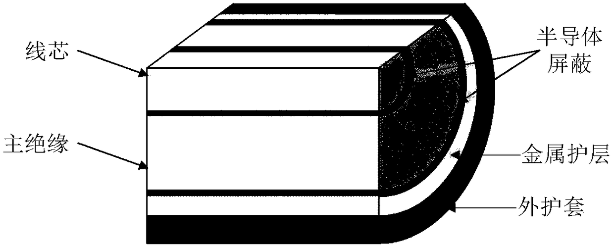
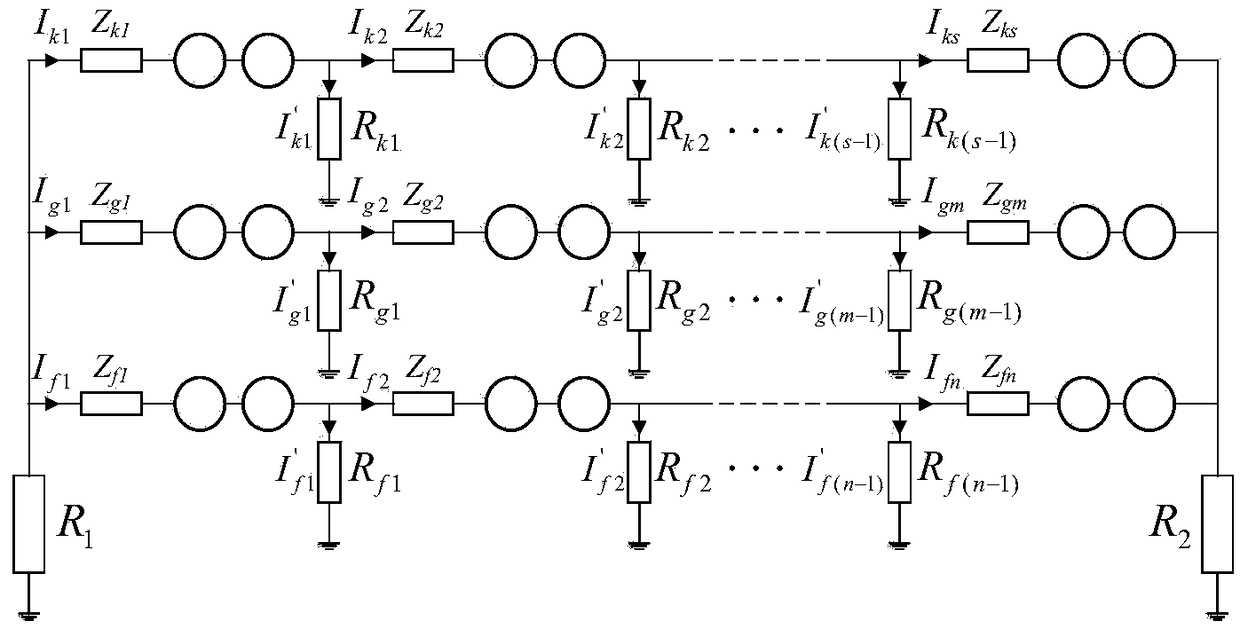
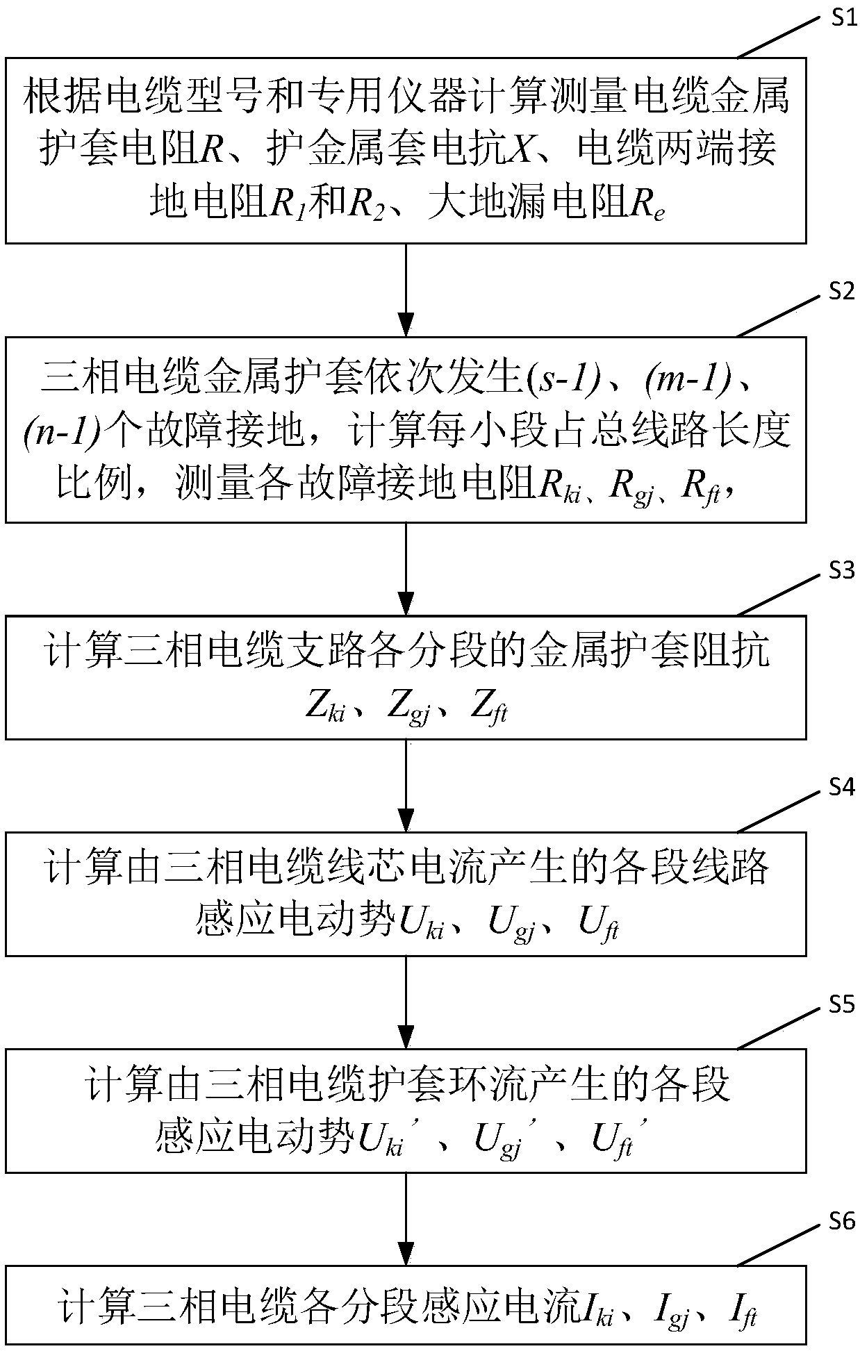
[0070] This embodiment discloses a method for calculating the induced current of the multi-phase multi-point grounding lower sheath of a cable metal sheath, such as figure 1 Shown is the most common structure of current power single-core cables, and this calculation method is applicable to such cables. Such as figure 2 Shown is the equivalent model of the induced current circuit. All calculation parameters, derivations and establishment of formulas in the present invention are developed around this circuit diagram to solve the numerical nature of each segment of the induced current in the case of multi-phase and multi-point grounding of the metal sheath of the power cable. The above is to solve this circuit. It specifically includes the following steps:

[0071] 1) Measure the grounding resistance R at both ends of the cable metal sheath 1 and R 2 , earth leakage resistance R e . This value can be read directly from the design index, and it is best to measure it on-site...


PUM


Abstract

The invention discloses a method for calculating the induced current of a metal sheath of a cable under multi-phase and multi-point grounding, which comprises the steps of S1, calculating and measuring the resistance R and reactance X of the metal sheath of the cable, the grounding resistance R1 and R2 at two ends of the cable and the earth leakage resistance Re; S2, calculating the length proportions [alpha]i, [beta]j and [gamma]t of each small section to the total line, and measuring fault grounding resistance Rki, Rgj and Rft; S3, calculating the metal sheath reactance Zki, Zgj and Zft of each section of the branches of the three-phase cable, and calculating circuit induced electromotive forces Uki, Ugj and Uft, which are generated by wire core current of the three-phase cable, of eachsection; S5, calculating induced electromotive forces Uki', Ugj' and Uft', which are generated by circulating current in the sheath of the three-phase cable, of each section; and S6, calculating induced current Iki, Igj and Ift of each section of the branches of the three-phase cable. The induced current value on each section of the cable under the multi-phase and multi-point grounding condition can be conveniently calculated according to the invention.

Description

technical field [0001] The invention relates to the technical field of power cables, in particular to a method for calculating induced currents of multi-phase and multi-point grounding undersheaths of cable metal sheaths. Background technique [0002] The induced current of the high-voltage cable sheath is an important part of the sheath circulation. Relevant standards have been formulated for the limit of the sheath circulation value in engineering. Excessive sheath circulation will lead to power loss, insulation aging, reduced current carrying capacity, and serious heating. It will even burn the ground wire, causing the power system to malfunction. [0003] At present, domestic and foreign scholars have proposed the calculation model and calculation method of the sheath induced current during the normal current-carrying operation of the high-voltage cable. The changing law and trend of current provide a reliable reference standard for cable design and operation. [0004]...

Claims


Application Information

Patent Timeline
Patent Type & Authority Applications(China)
IPC IPC(8): G01R19/00
CPCG01R19/00
Inventor 杨帆刘刚朱宁西
Owner SOUTH CHINA UNIV OF TECH
Why Eureka
Try Eureka