
Device of measuring laser optical fiber transmission

A technology for optical fiber transmission and laser measurement, applied in the field of laser measurement, can solve the problems of complicated operation process, low efficiency of fiber coupling and adjustment, no relatively standardized installation and adjustment standards, etc., to achieve the effect of improving installation and adjustment efficiency and simplifying installation and adjustment time.

Active Publication Date: 2018-11-02
CHANGCHUN INST OF OPTICS FINE MECHANICS & PHYSICS CHINESE ACAD OF SCI
View PDF5 Cites 6 Cited by
  • Summary
  • Abstract
  • Description
  • Claims
  • Application Information

AI Technical Summary

Problems solved by technology

At present, in the optical fiber coupling operation, it usually relies on the installation and adjustment experience of professional operators to artificially estimate the transmission effect of the laser in the optical fiber, and then repeatedly measures the spot size of the fiber through CCD and other measuring equipment until it meets the requirements. There is no such thing in the traditional process. Relatively standardized installation and adjustment standards, the operation process is complicated, resulting in low efficiency of fiber coupling installation and adjustment

Method used


Image

  • Device of measuring laser optical fiber transmission
  • Device of measuring laser optical fiber transmission
  • Device of measuring laser optical fiber transmission

Examples


Embodiment Construction

[0024] The core of the invention is to provide a device for measuring laser fiber transmission, so as to improve the efficiency of fiber coupling and adjustment.

[0025] In order to enable those skilled in the art to better understand the technical solutions of the present invention, the present invention will be further described in detail below in conjunction with the accompanying drawings and embodiments.

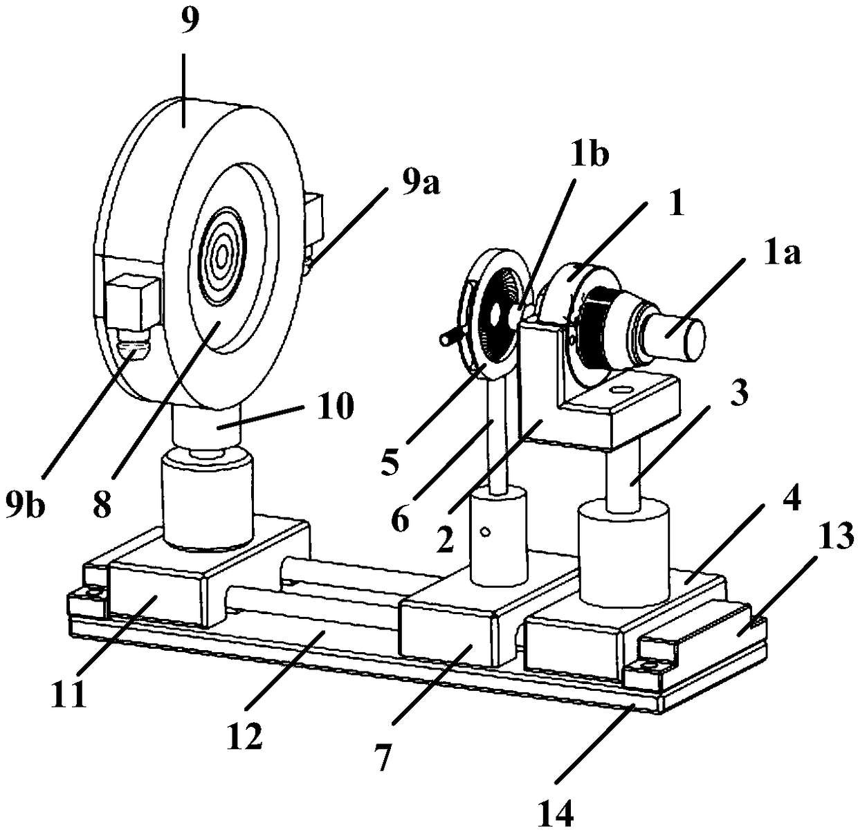
[0026] Please refer to Figure 1 to Figure 4 , in a specific embodiment, the device for measuring laser fiber transmission provided by a specific embodiment of the present invention includes an aperture 5, a laser emitting unit provided with an optical fiber connector 1, and a beam receiving screen 8 for receiving laser light; the aperture 5 It is detachably located at the front end of the light exit 1b of the laser exit unit, and is used to measure the core diameter of the optical fiber 1a. Specifically, when measuring the core diameter of the optical fiber 1a, the cen...


PUM


Abstract

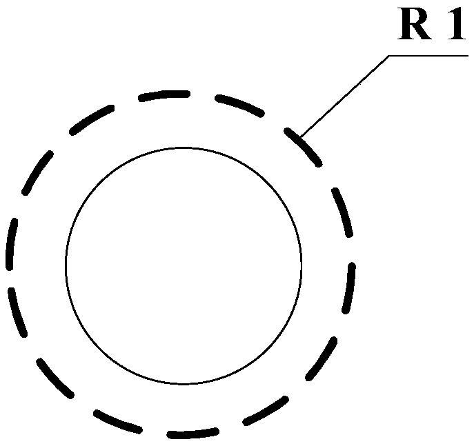
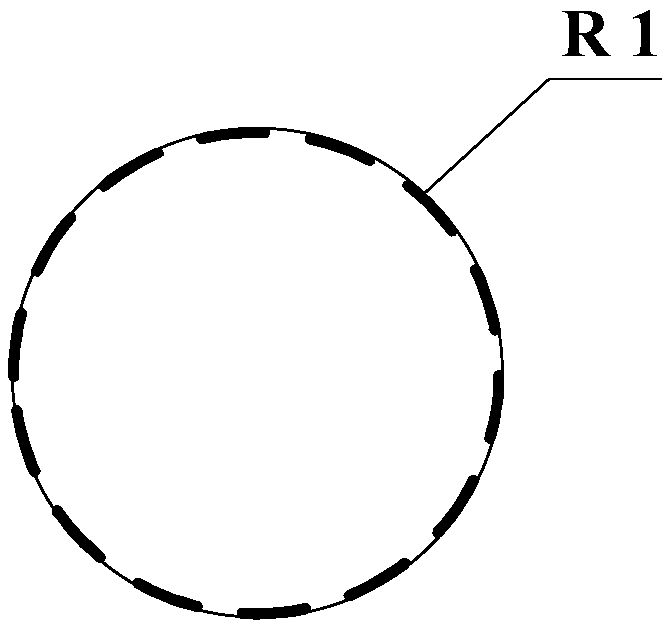
The invention discloses a device of measuring laser optical fiber transmission. The device comprises a diaphragm, a laser emitting unit provided with an optical fiber connector and a beam receiving screen used for receiving laser; the diaphragm is detachably located at the front end of a laser outlet of the laser emitting unit and is used for measuring an optical fiber core diameter; the beam receiving screen is provided with a round mark with the center thereof collinear with the axis of the optical fiber connector; and the radius of the round mark is a spot radius of emitted laser when the laser enters via an optical fiber critical angle. In the device of measuring the laser optical fiber transmission, the optical fiber core diameter is measured by the diaphragm, then the corresponding round mark is further obtained, and the optical fiber is irradiated by the laser. By comparing the image of the optical fiber connector at the beam receiving screen with the round mark, a transmissionmode of the laser in the optical fiber can be obtained rapidly, time taken for adjusting optical fiber coupling is simplified, and the optical fiber coupling adjustment efficiency is increased.

Description

technical field [0001] The invention relates to the technical field of laser measurement, in particular to a device for measuring laser optical fiber transmission. Background technique [0002] As a light transmission tool, optical fiber is widely used due to its characteristics of long-distance transmission, low energy loss, flexible transmission and higher safety. Laser processing equipment for optical fiber transmission has been widely used in industry, medical treatment, aviation, etc. Many fields. [0003] In view of the wide range of applications of optical fibers, under the dual market demands of mass industrialization and high coupling efficiency, higher installation and adjustment requirements are put forward for operators. At present, in the optical fiber coupling operation, it usually relies on the installation and adjustment experience of professional operators to artificially estimate the transmission effect of the laser in the optical fiber, and then repeatedl...

Claims


Application Information

Patent Timeline
Patent Type & Authority Applications(China)
IPC IPC(8): H04B10/079
CPCH04B10/0795
Inventor 朱洪波张亚维王彪林星辰宁永强秦莉
Owner CHANGCHUN INST OF OPTICS FINE MECHANICS & PHYSICS CHINESE ACAD OF SCI
Learn More