
Axial-flow-fan training model

An axial flow fan and model technology, applied in mine/tunnel ventilation, mining equipment, earth-moving drilling, etc., can solve the problems of lack of on-site experience of maintenance workers, inability to handle in time, and few operating opportunities, and achieve the cultivation of operating experience and The effect of feel

Active Publication Date: 2018-10-23
兖矿能源集团股份有限公司
View PDF5 Cites 0 Cited by
  • Summary
  • Abstract
  • Description
  • Claims
  • Application Information

AI Technical Summary

Problems solved by technology

There are few on-site operation opportunities for employees, low safety, and lack of on-site experience for maintenance workers, resulting in failure to deal with accidents in time, affecting mine safety and production

Method used


Image

  • Axial-flow-fan training model
  • Axial-flow-fan training model
  • Axial-flow-fan training model

Examples


Embodiment approach 1

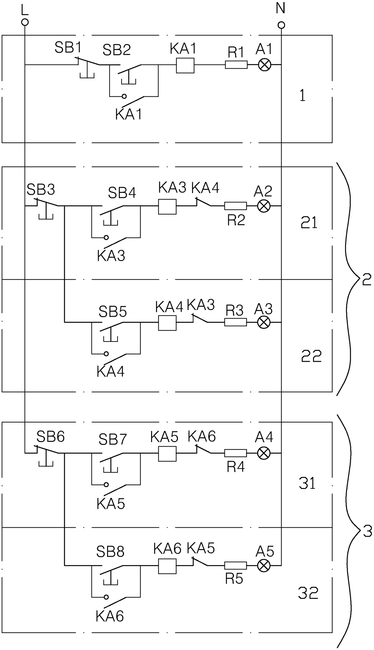
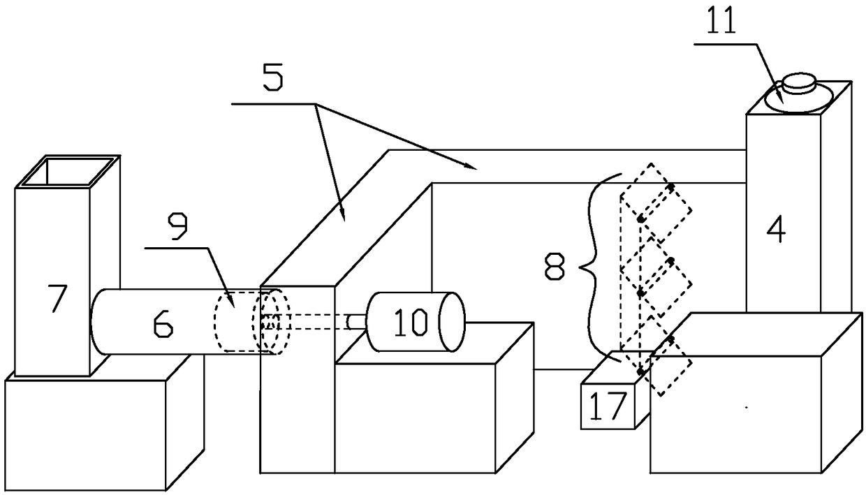
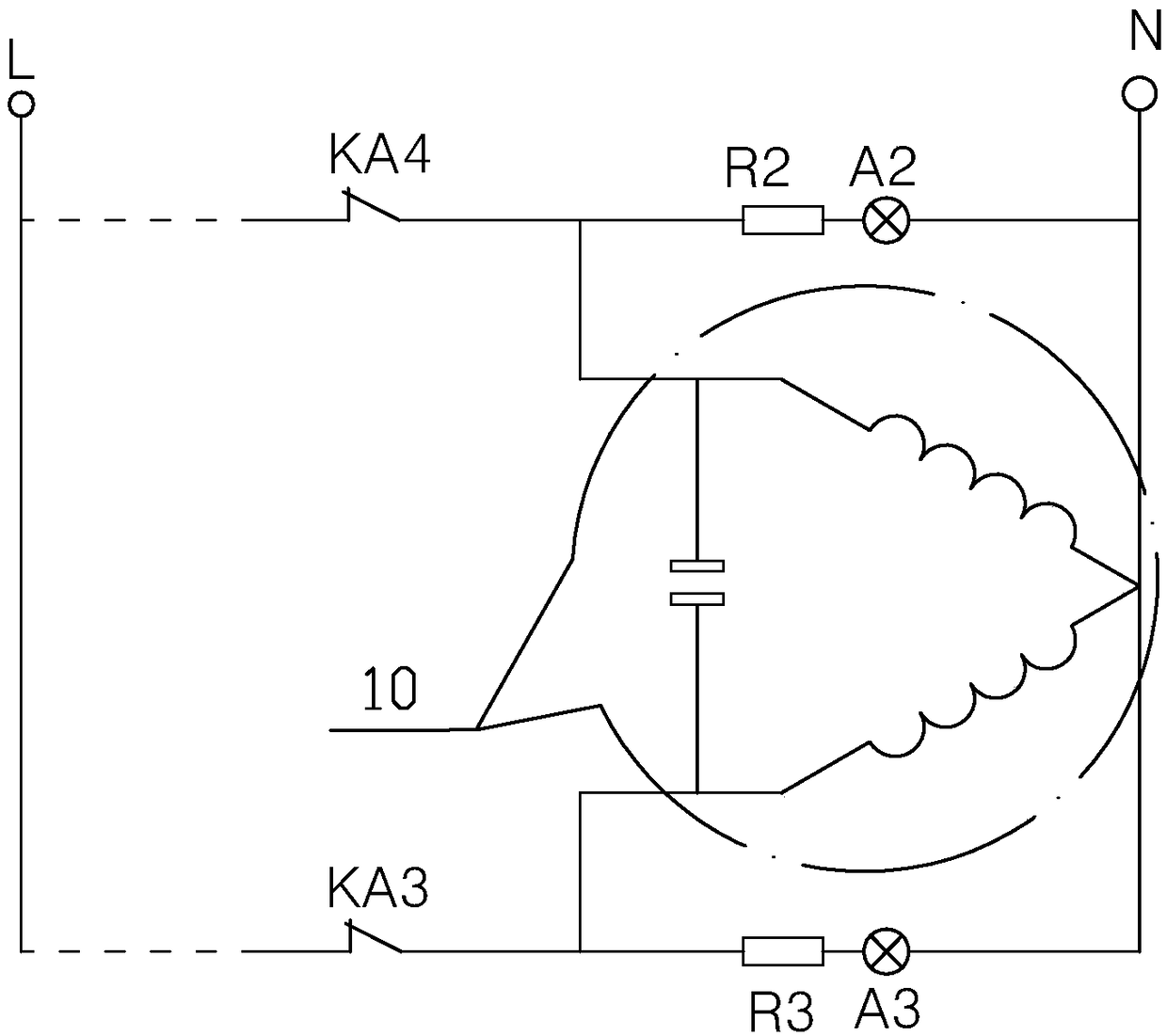
[0028] Implementation mode one: if Figure 1-3 As shown, the axial flow fan training model includes an axial flow fan control circuit, and the axial flow fan control circuit includes a hydraulic pump station manual control analog circuit 1, a fan manual control analog circuit 2, and a damper manual control analog circuit 3. It is characterized in that: Including air shaft model 4, air channel box 5, diffusion cylinder 6, diffusion tower model 7, the above components are connected in sequence, and the end of the air channel box 5 adjacent to the air shaft model 4 is provided with a damper 8,

[0029] The hydraulic pump station manual control analog circuit 1 includes a normally closed button switch SB1, a normally open button switch SB2, a normally open relay switch KA1, a resistor R1 and a hydraulic station indicator light A1, and the normally open relay switch KA1 includes a normally open armature switch And the coil, wherein the normally open armature switch of the normally ...

Embodiment approach 2

[0049] Implementation mode two: if Figure 4 As shown, the axial flow fan training model also includes PLC, manual switches K1, K2 and normally closed relay switch KA2, the normally closed relay switch KA2 includes a normally closed armature switch and a coil, and the PLC includes at least five module switches 12 , 13, 14, 15, 16, after the normally closed button switches SB1, SB3, SB6 are interconnected, the normally closed armature switch of the normally closed relay switch KA2 and the manual switch K1 are connected to the live wire L of the power supply, and the PLC After the five modular switches 12, 13, 14, 15, 16 are connected in parallel, they are connected to the fire wire L of the power supply through the manual switch K2.

[0050] The other end of the module switch 12 is connected to the contact between the normally open armature switch of the normally open relay switch KA1 and the coil; the other end of the module switch 13 is connected to the contact between the no...


PUM


Abstract

The invention relates to an axial-flow-fan training model. For filling the void of the prior art and solving the technical problems, the axial-flow-fan training model comprises an axial-flow-fan control circuit, and the axial-flow-fan control circuit comprises a hydraulic-pump-station manual control analog circuit, a fan manual control analog circuit and an air-door manual control analog circuit.The axial-flow-fan training model is characterized by also comprising an air shaft model, an air flue box, a diffusion cylinder and a diffusion cylinder model, all the parts are sequentially communicated, an air door is arranged at the end, close to the air shaft model, of the air flue box, and the fan manual control analog circuit comprises a fan forward indicating circuit and a fan reverse indicating circuit; the air-door manual control analog circuit comprises an air-door opening indicating circuit and an air-door closing indicating circuit. According to the axial-flow-fan training model, operational experiences and hand feelings of workers are conveniently cultivated, and the axial-flow-fan training model is widely suitable for all coal mines.

Description

technical field [0001] The invention relates to a training model of an axial fan. Background technique [0002] The main ventilator in the current coal mine mostly adopts the axial flow fan with adjustable blades. Its control logic is relatively complex and the degree of automation is high. The operation of starting, stopping and reversing all realizes one-button operation. In accordance with the requirements of the "Coal Mine Safety Regulations" and "Mine Quality Standardization", the main ventilator in the mine is turned down and inspected once a month. Daily operation and maintenance frequency is low. [0003] According to relevant regulations: if the main ventilator stops for more than 10 minutes, it is a major electromechanical accident. Due to the particularity and importance of the ventilation system in mine production, in actual production, the main ventilator cannot be simulated and operated on site. There are few on-site operation opportunities for employees, lo...

Claims


Application Information

Patent Timeline
IPC IPC(8): E21F1/02
CPCE21F1/02
Inventor 董军骆建营王青玉赵慧杰闵祥晟蒋述志岳福森许健
Owner 兖矿能源集团股份有限公司
Learn More