
Synthetic leather wet production line ironing wheel transmission equipment

A technology of transmission equipment and synthetic leather, applied in textiles and papermaking, etc., can solve the problems of inseparability, the transmission device is not equipped with automatic heat dissipation function, and the working status of the components in the device cannot be known in real time, so as to achieve the effect of convenient inspection and maintenance.

Inactive Publication Date: 2018-09-28
侯如升
View PDF4 Cites 0 Cited by
  • Summary
  • Abstract
  • Description
  • Claims
  • Application Information

AI Technical Summary

Problems solved by technology

[0002] Synthetic leather is a plastic product that simulates the composition and structure of natural leather and can be used as its substitute material. It is usually made of impregnated non-woven fabric as a mesh layer and a microporous polyurethane layer as a grain layer. They are very similar to leather and have a certain degree of air permeability. They are closer to natural leather than ordinary artificial leather. They are widely used in the production of shoes, boots, bags and balls. Synthetic leather needs to use many components during production. Wet ironing The flat wheel is one of them. The wet line ironing wheel cannot be separated from the transmission device when it is working. The traditional transmission device is not equipped with an automatic heat dissipation function, which cannot discharge the heat in the device in time. At the same time, it is not equipped with a video monitoring function. Understand the working status of the components in the device in real time, so a synthetic leather wet normal line ironing wheel transmission equipment is needed

Method used


Image

  • Synthetic leather wet production line ironing wheel transmission equipment
  • Synthetic leather wet production line ironing wheel transmission equipment
  • Synthetic leather wet production line ironing wheel transmission equipment

Examples


Embodiment Construction

[0018] The present invention will be further described below in conjunction with accompanying drawing:

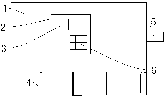
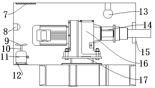
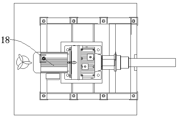
[0019] Such as Figure 1-Figure 3 As shown, a synthetic leather wet normal ironing wheel transmission device includes a base 4, a protective cover 1 and a cooling net 7, the top surface of the base 4 is provided with a protective cover 1, and the inner bottom surface of the protective cover 1 is provided with a mounting seat 17 , the mounting base 17 is provided with a reducer 16, the side of the reducer 16 is provided with a drive motor 18, the other side of the reducer 16 is provided with a coupling 14, the end of the coupling 14 is provided with a drive shaft 5, and the outside of the drive shaft 5 A sealing ring 15 is provided, a motor frame 12 is provided on the side of the mounting base 17, a servo motor 11 is provided on the motor frame 12, a rotating shaft 10 is provided at the end of the servo motor 11, and a fan blade 9 is provided at the end of the rotating shaft...


PUM


Abstract

The invention discloses synthetic leather wet production line ironing wheel transmission equipment, which comprises a pedestal, a protective cover and a radiator-grid. The top surface of the pedestalis provided with the protective cover. A mounting base is arranged at the bottom inside the protective cover. A reducer is arranged on the mounting base. A driving motor is arranged at one side surface of the reducer, and a shaft coupling is disposed at the other side surface of the reducer. A driving shaft is arranged at an end portion of the shaft coupling. A sealing ring is arranged at outer side of the driving shaft. A motor seat is arranged at one side of the mounting base. The invention has the following beneficial effects: through a feedback control loop composed of a temperature sensor, a control host and a servo motor, fan blades can be automatically controlled to rotate when temperature in the equipment reaches a preset starting value and then heat in the equipment is dischargedto the outside; and with the arrangement of an infrared camera, video information of working condition of components in the equipment can be acquired at real time and the video information can be displayed on a display screen such that users can conveniently check for maintenance.

Description

technical field [0001] The invention relates to the field of synthetic leather production auxiliary devices, in particular to a synthetic leather wet normal ironing wheel transmission device. Background technique [0002] Synthetic leather is a plastic product that simulates the composition and structure of natural leather and can be used as its substitute material. It is usually made of impregnated non-woven fabric as a mesh layer and a microporous polyurethane layer as a grain layer. They are very similar to leather and have a certain degree of air permeability. They are closer to natural leather than ordinary artificial leather. They are widely used in the production of shoes, boots, bags and balls. Synthetic leather needs to use many components during production. Wet ironing The flat wheel is one of them. The wet line ironing wheel cannot be separated from the transmission device when it is working. The traditional transmission device is not equipped with an automatic he...

Claims


Application Information

Patent Timeline
Patent Type & Authority Applications(China)
IPC IPC(8): D06N3/00
CPCD06N3/0077
Inventor 侯如升
Owner 侯如升
Learn More