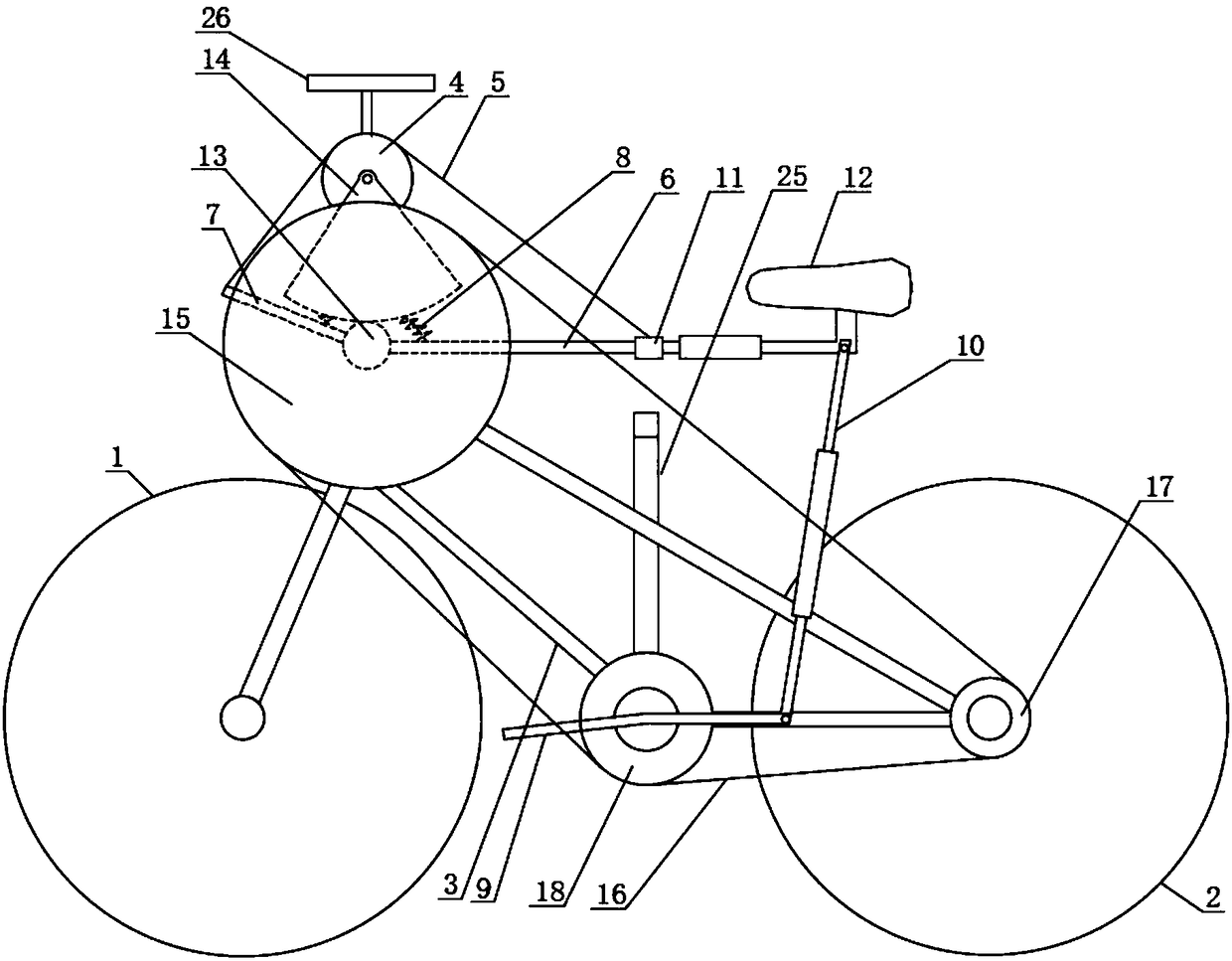
Labor-saving bicycle with adjustable speed
A bicycle and speed technology, applied in vehicle parts, vehicle gearboxes, chain/belt drives, etc., can solve the problems of increased risk, difficult speed regulation, and no corresponding speed regulation mechanism, and achieve the effect of simple and fast speed regulation.
- Summary
- Abstract
- Description
- Claims
- Application Information
AI Technical Summary
Problems solved by technology
Method used
Image
Examples
Embodiment 1
[0036] Such as figure 1 As shown, a speed-adjustable labor-saving bicycle includes a front wheel assembly 1, a rear wheel assembly 2 and a vehicle frame 3, and the front wheel assembly 1 and the rear wheel assembly 2 are respectively installed at the front and rear ends of the vehicle frame 3 .
[0037] Specifically, the front wheel assembly 1 and the rear wheel assembly 2 are conventional bicycle wheel structures, both including a wheel axle, spokes, rims and tires, the tires are fixed on the rims, and the rims are fixed on the wheel axles through the spokes. The vehicle frame 3 is a tripod. The stability of the triangle ensures that the overall structure of the bicycle is firm and reliable. The top of the front end of the vehicle frame 3 is fixed with a handle 26 .
[0038] It also includes a four-bar linkage mechanism, a sprocket 4, a chain A5 and a transmission mechanism for converting the rider's own weight into a swing force, the four-bar linkage mechanism is installe...
Embodiment 2
[0053] Such as figure 2 As shown, the difference between this embodiment and Embodiment 1 is that the transmission mechanism also includes an intermediate flywheel 18, a rotating shaft extends vertically at the rotational connection between the pedal 9 and the vehicle frame 3, and the intermediate flywheel 18 is fixedly sleeved on the rotating shaft , Flywheel B15, middle flywheel 18 and flywheel C17 are connected by chain B16 transmission.
[0054] Specifically, when riding, the size of the output torque can be adjusted directly by adjusting the position of the slider 11 relative to the output link rod 6, thereby completing the adjustment of the speed. The slider 11 slides arbitrarily on the output link rod 6 to ensure the speed The adjustment can be stepless speed regulation, which is more suitable for the rider's needs.
Embodiment 3
[0056] Such as image 3 As shown, the difference between this embodiment and Embodiment 1 is that the transmission mechanism includes a chain C23, a chain D24, a flywheel E20, a flywheel D22, a transition flywheel 19 and an intermediate chain plate 21, and the rotational connection between the pedal 9 and the vehicle frame 3 There is a rotating shaft extending vertically. The transition flywheel 19 is sleeved on the rotation shaft. The intermediate chain plate 21 is arranged coaxially with the transition flywheel 19 and is fixedly connected to the outer disc body of the transition flywheel 19. The flywheel E20 is fixedly connected coaxially with the flywheel A13. The flywheel The diameter of E20 is larger than the diameter of flywheel A13. Flywheel E20 is connected to transition flywheel 19 through chain C23. The middle chain disc 21 is connected to flywheel D22 through chain D24. Flywheel D22 is connected to rear wheel assembly 2. The diameter of flywheel E20 is larger than th...
PUM
 Abstract
Description
Claims
Application Information
 - R&D
- Intellectual Property
- Life Sciences
- Materials
- Tech Scout
- Unparalleled Data Quality
- Higher Quality Content
- 60% Fewer Hallucinations
Browse by: Latest US Patents, China's latest patents, Technical Efficacy Thesaurus, Application Domain, Technology Topic, Popular Technical Reports.
© 2025 PatSnap. All rights reserved.Legal|Privacy policy|Modern Slavery Act Transparency Statement|Sitemap|About US| Contact US: help@patsnap.com


