
Laying tool

A technology for tooling and positioning elements, which is applied in the field of laying tooling for laying main beam glass fiber cloth, and can solve the problems of low laying efficiency and the like

Pending Publication Date: 2018-09-07
SHANGHAI AEOLON WIND ENERGY TECH DEVGRP CO LTD
View PDF0 Cites 0 Cited by
  • Summary
  • Abstract
  • Description
  • Claims
  • Application Information

AI Technical Summary

Problems solved by technology

[0004] The technical problem to be solved by the present invention is to provide a laying tool to overcome the defect of low laying efficiency in the laying of the main beam glass fiber cloth in the prior art

Method used


Image

  • Laying tool

Examples


Embodiment Construction

[0042] A preferred embodiment will be given below, and the present invention will be described more clearly and completely in conjunction with the accompanying drawings.

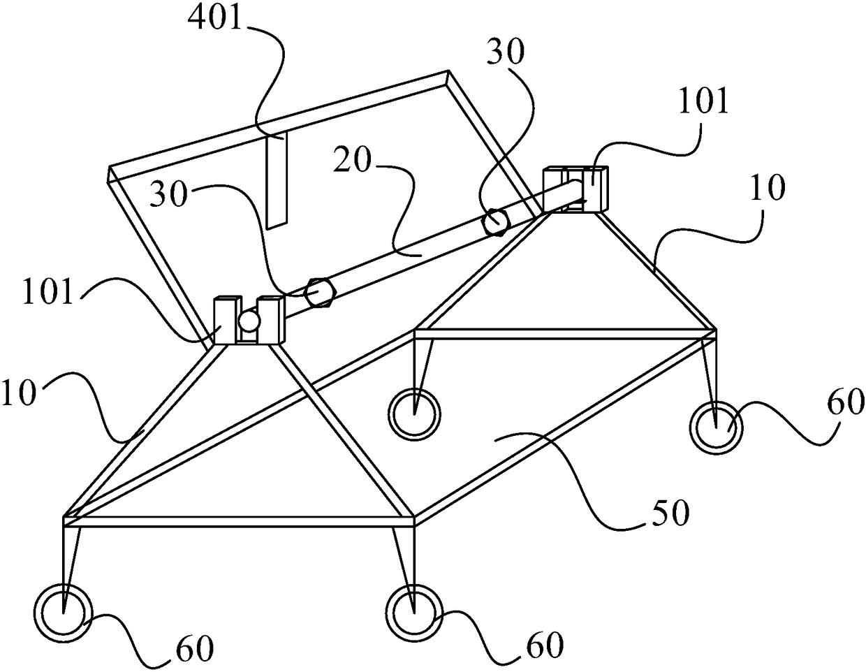
[0043] This embodiment discloses a laying tool, the laying tool is used for laying glass fiber cloth for the main beam of the wind power blade, refer to figure 1 It should be understood that the laying tool includes two supporting frames 10 , a connecting shaft 20 and a driving member (not shown in the figure) disposed opposite to each other. Wherein, the top of the support frame 10 has a support block 101, and the two ends of the connecting shaft 20 correspond to the two supporting blocks 101, the connecting shaft 20 is used to pass through the reel of the glass fiber cloth, and the driving member is used to act on The outlet end of the fiberglass cloth. Wherein, in this embodiment, the driving member is a motor.

[0044] In this embodiment, the reel of glass fiber cloth is sleeved on the connecting shaft...


PUM


Abstract

The invention provides a laying tool. The laying tool is suitable for laying glass cloth for a girder of wind turbine blades. The laying tool includes a connecting shaft, a driving assembly and two supporting frames oppositely arranged. Supporting blocks are arranged on the tops of the supporting frames, the two ends of the connecting shaft penetrate through the two supporting blocks in one-to-onecorrespondence; the connecting shaft is used for being arranged in a coiling block of the glass cloth in a penetrating mode; the driving assembly acts on the cloth-out end of the glass cloth. The connecting shaft is sleeved with the coiling block of the glass cloth and the driving assembly acts on the cloth-out end; under the effect of the driving assembly, the glass cloth rotates relative to theconnecting shaft, automatic stretching of the glass cloth can be achieved, automatic laying of the glass cloth can be better achieved and the laying efficiency can be improved.

Description

technical field [0001] The invention relates to the field of wind power blades, in particular to a laying tool for laying main beam glass fiber cloth. Background technique [0002] After years of development, wind power generation technology has developed to the megawatt level, and wind power blades play a pivotal role in wind power generation technology. At present, the composition of wind turbine blades is divided into five parts: root end, main beam, web, leading edge shell, and trailing edge shell. As the main load-bearing position of wind turbine blades, the main girder has higher and higher requirements for quality, production efficiency and precision. In the current manufacturing process of the prefabricated main girder of wind power blades, the laying of the glass fiber cloth of the main girder has always relied on manual operation and positioning with a ruler. This laying method is greatly affected by the operating level of the operator, prone to inaccurate positi...

Claims


Application Information

Patent Timeline
Patent Type & Authority Applications(China)
IPC IPC(8): B29C70/38B29C70/54
CPCB29C70/38B29C70/543
Inventor 陆泉龙张超刘炳
Owner SHANGHAI AEOLON WIND ENERGY TECH DEVGRP CO LTD
Learn More