
Measurement system and method of OSNR of any point in optical fiber communication link

A fiber optic communication and measurement system technology, applied in transmission systems, electromagnetic wave transmission systems, electrical components, etc., can solve the problems of difficult to achieve OSNR measurement at any point of the link, frequency band utilization has nothing to do with modulation format, and difficult to measure accurately , to achieve the effect of improving measurement accuracy, good applicability and flexible use

Active Publication Date: 2018-08-21
WUHAN POST & TELECOMM RES INST CO LTD
View PDF6 Cites 3 Cited by
  • Summary
  • Abstract
  • Description
  • Claims
  • Application Information

AI Technical Summary

Problems solved by technology

[0005] The purpose of the present invention is to overcome the deficiency of above-mentioned background technology, provide a kind of measurement system and method of OSNR of arbitrary point in the optical fiber communication link, aim at solving existing OSNR measurement method, because noise is very big, OSNR is very small, However, it is difficult to measure accurately and the existing advantages of OSNR monitoring range, frequency band utilization and modulation format are not available at the same time, and it is difficult to realize the problem of OSNR measurement at any point of the link

Method used


Image

  • Measurement system and method of OSNR of any point in optical fiber communication link
  • Measurement system and method of OSNR of any point in optical fiber communication link
  • Measurement system and method of OSNR of any point in optical fiber communication link

Examples


Embodiment Construction

[0038] The present invention will be further described in detail below in conjunction with the accompanying drawings and specific embodiments.

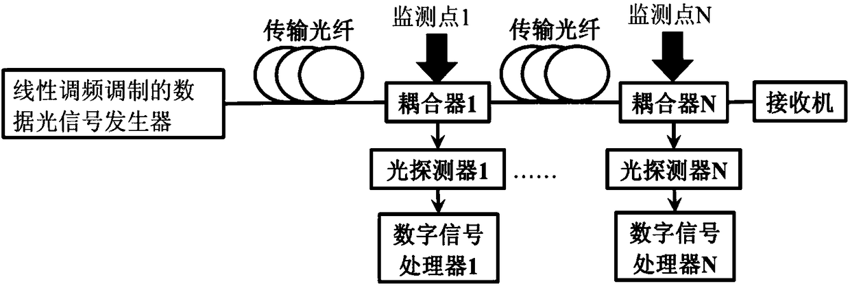
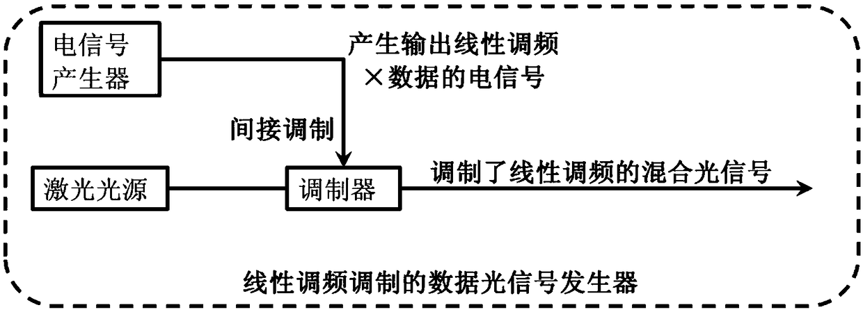
[0039] see figure 1 As shown, the embodiment of the present invention provides a measurement system of OSNR at any point in an optical fiber communication link, including a data optical signal generator arranged at the transmitting end and a receiver arranged at the receiving end, the receiver and the chirp modulating The data optical signal generators are connected by a transmission fiber, and at least one monitoring point is set in the transmission fiber, and each monitoring point can be located at any position in the transmission fiber. like figure 1 As shown in , monitoring point 1 to monitoring point N represent N monitoring points at any position in the transmission fiber (N is a positive integer greater than 1). In practical applications, the number N of monitoring points can be determined according to specific monitoring need...


PUM


Abstract

The invention discloses a measurement system and method of an OSNR of any point in an optical fiber communication link, and relates to the technical field of optical fiber communication. The measurement system comprises: a linear frequency modulation modulated data optical signal generator and a receiver, the receiver and the linear frequency modulation modulated data optical signal generator areconnected by a transmission optical fiber, at least one monitoring point is disposed in the transmission optical fiber, and each monitoring point can be located at any position in the transmission optical fiber. A coupler, a photodetector and a digital signal processor are arranged at each monitoring point; the coupler is used for dividing a hybrid optical signal into a normally transmitted optical signal and a detection signal; the photodetector is used for receiving the detection signal; the digital signal processor is used for calculating an OSNR value at the monitoring point according to atotal power value of the detection signal, the power of a linear frequency modulation signal in the detection signal and the power of a data signal in the detection signal. By adoption of the measurement system and method disclosed by the invention, the OSNR of any point in the optical fiber communication link can be flexibly and accurately measured.

Description

technical field [0001] The invention relates to the technical field of optical fiber communication, in particular to a system and method for measuring OSNR (Optical Signal Noise Ratio, Optical Signal Noise Ratio) at any point in an optical fiber communication link. Background technique [0002] With the continuous development of optical transmission systems, various technologies such as wavelength division multiplexing, frequency division multiplexing, polarization multiplexing technology, and high-order modulation format signals have been applied to improve the communication capacity of optical transmission systems. With the continuous increase of optical communication capacity, optical transmission systems have higher and higher requirements for optical performance monitoring (Optical Performance Monitoring, OPM). Since the bit error rate of the signal in optical performance detection is a parameter most concerned by the receiving end, and the cost of directly detecting th...

Claims


Application Information

Patent Timeline
Patent Type & Authority Applications(China)
IPC IPC(8): H04B10/079
Inventor 李蔚余少华
Owner WUHAN POST & TELECOMM RES INST CO LTD
Learn More