
Measuring device for mechanoluminescent performance of luminescent material

A technology of a luminescent material and a detection device, which is applied in the detection field, can solve the problems of unable to display force signal and light signal synchronously, influence the monitoring results of ferroluminescence performance, and inconvenience of ultraviolet lamp excitation, etc., and achieves stable sample and small error in test results. , the effect of improving accuracy

Active Publication Date: 2021-01-19
SOUTH CHINA UNIV OF TECH
View PDF12 Cites 0 Cited by
  • Summary
  • Abstract
  • Description
  • Claims
  • Application Information

AI Technical Summary

Problems solved by technology

However, this cannot complete the excitation of the ultraviolet lamp conveniently and quickly, and the recording and monitoring of the test process are slow, and the force signal and the light signal cannot be displayed synchronously, which affects the monitoring results of the mechanoluminescence performance and limits its application to a certain extent.

Method used


Image

  • Measuring device for mechanoluminescent performance of luminescent material
  • Measuring device for mechanoluminescent performance of luminescent material
  • Measuring device for mechanoluminescent performance of luminescent material

Examples


Embodiment Construction

[0023] The present invention will be further described in detail below in conjunction with the accompanying drawings.

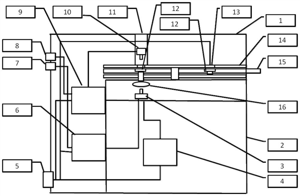
[0024] A detection device for the mechanoluminescent performance of luminescent materials, which includes a dark box, a stage, an ultraviolet lamp, a pressure signal monitoring system, and an optical signal monitoring system; the stage is used to install samples; the ultraviolet lamp is set in the dark box; pressure signal monitoring The system and the optical signal monitoring system are set in the dark box, and both have signal output terminals, and the signal output ends are installed on the outer wall of the dark box.

[0025] The camera obscura includes an inner camera camera and an outer camera camera, the inner camera camera is installed in the outer camera camera, and the inner camera camera is located at the bottom right corner of the outer camera camera. The volume of inner layer obscura is smaller than the volume of outer layer obscura. The upper ...


PUM


Abstract

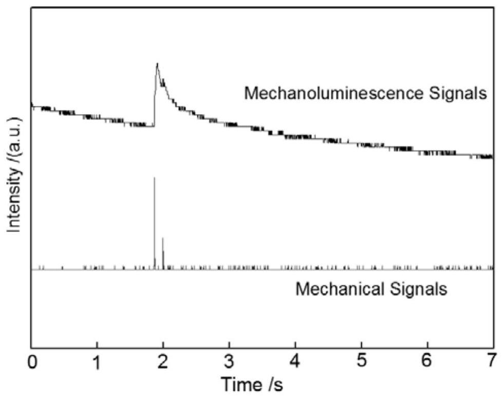
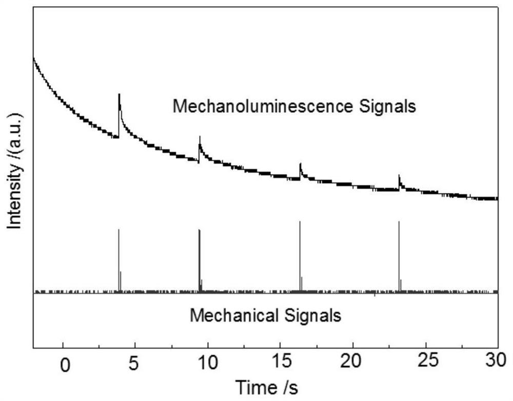
The invention relates to an apparatus for detecting mechanoluminescent performance of a luminescent material. The apparatus comprises a dark chamber, an objective table, an ultraviolet lamp, a pressure signal monitoring system, and an optical signal monitoring system; the dark chamber comprises an internal layer dark chamber and an external layer dark chamber, the internal layer dark chamber is placed at one side of the bottom of the external layer dark chamber, and the ultraviolet lamp is arranged in the external layer dark chamber and positioned over the internal layer dark chamber; the pressure transducer is arranged in the external layer dark chamber, and opposites a force application port over the external layer dark chamber, a pressure signal output port is arranged at an outer wallof the external layer dark chamber, and the pressure transducer, a pressure transmitter and the pressure signal output port are electrically connected in order; an objective table is arranged over theinternal layer dark chamber, a sample installation groove is arranged at the objective table, the sample installation groove and the force application port over the external layer dark chamber, and the pressure transducer are coaxially arranged. The apparatus has the advantages that simultaneous and synchronous monitoring is carried out, a pressure signal of mechanical excitation force and the generated optical signal are recorded, and the monitoring result is accurate. The apparatus belongs to the technical field of detection.

Description

technical field [0001] The invention belongs to the technical field of detection, and in particular relates to a detection device for the mechanoluminescence performance of a luminescent material. Background technique [0002] The mechanoluminescence performance means that the luminescent material emits light when it is subjected to mechanical forces such as impact, compression, friction, and cutting. The phenomenon of mechanoluminescence has been discovered more than 400 years ago. Many inorganic and organic compounds will emit light under the action of crushing or mechanical stress. These mechanoluminescent compounds include conductors, semiconductors and insulators. The mechanoluminescence phenomenon of materials has aroused great interest and attention of researchers in the fields of mechanical engineering, material fracture and earthquake prediction and monitoring, life science and medical diagnosis. When testing the mechanoluminescent properties of luminescent materia...

Claims


Application Information

Patent Timeline
Patent Type & Authority Patents(China)
IPC IPC(8): G01N21/70G01N21/01
CPCG01N21/01G01N21/70
Inventor 潘志东吕海涛苏洪炎李萍王燕民
Owner SOUTH CHINA UNIV OF TECH
Learn More