Control cabinet for printing equipment

A technology of printing and dyeing equipment and control cabinet, which is applied in the field of control cabinets for printing and dyeing equipment, can solve problems such as inconvenience for users to use, and achieve the effect of convenient movable connection and convenient use.

Inactive Publication Date: 2018-08-14
叶侃
View PDF0 Cites 0 Cited by
  • Summary
  • Abstract
  • Description
  • Claims
  • Application Information

AI Technical Summary

Problems solved by technology

[0004] The object of the present invention is to provide a control cabinet for printing and dyeing equipment, which has the advantage of being convenient for users to use, and solves the problem that the existing control cabinet for printing and dyeing equipment is not convenient for users to use

Method used


Image

  • Control cabinet for printing equipment
  • Control cabinet for printing equipment
  • Control cabinet for printing equipment

Examples


Embodiment Construction

[0018] The following will clearly and completely describe the technical solutions in the embodiments of the present invention with reference to the accompanying drawings in the embodiments of the present invention. Obviously, the described embodiments are only some, not all, embodiments of the present invention. Based on the embodiments of the present invention, all other embodiments obtained by persons of ordinary skill in the art without making creative efforts belong to the protection scope of the present invention.

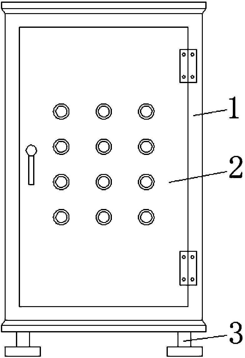
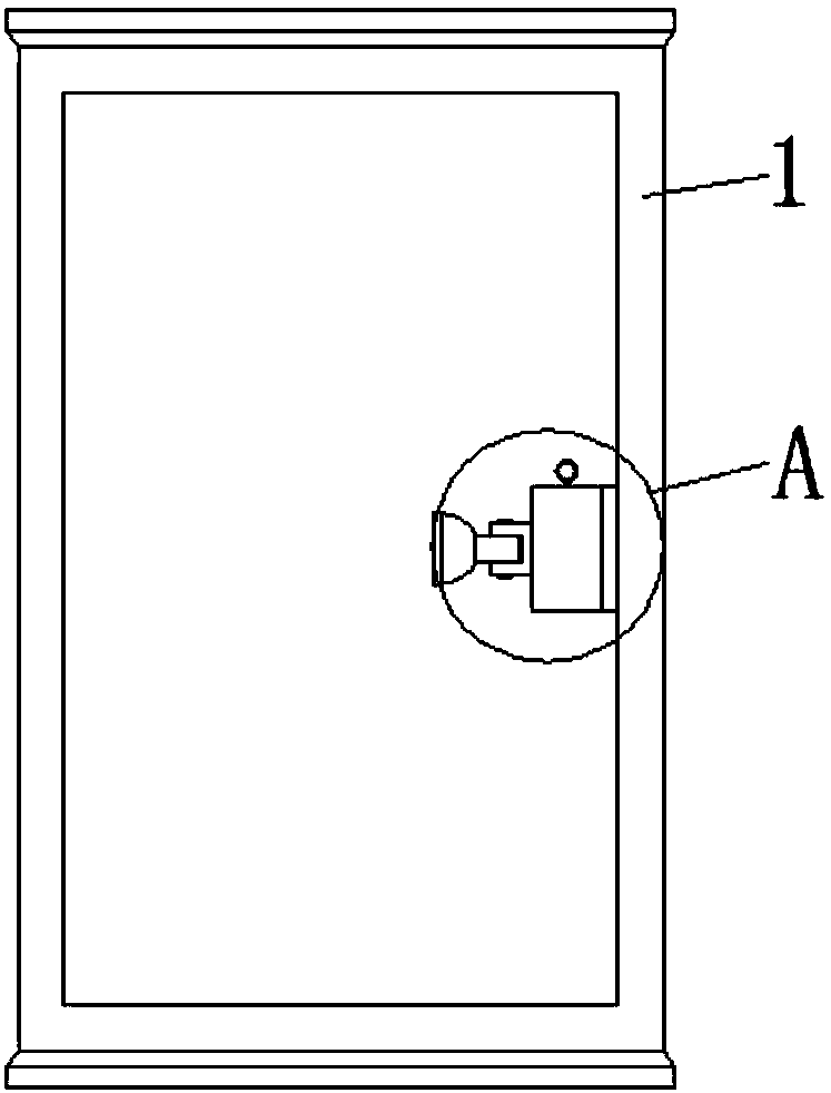
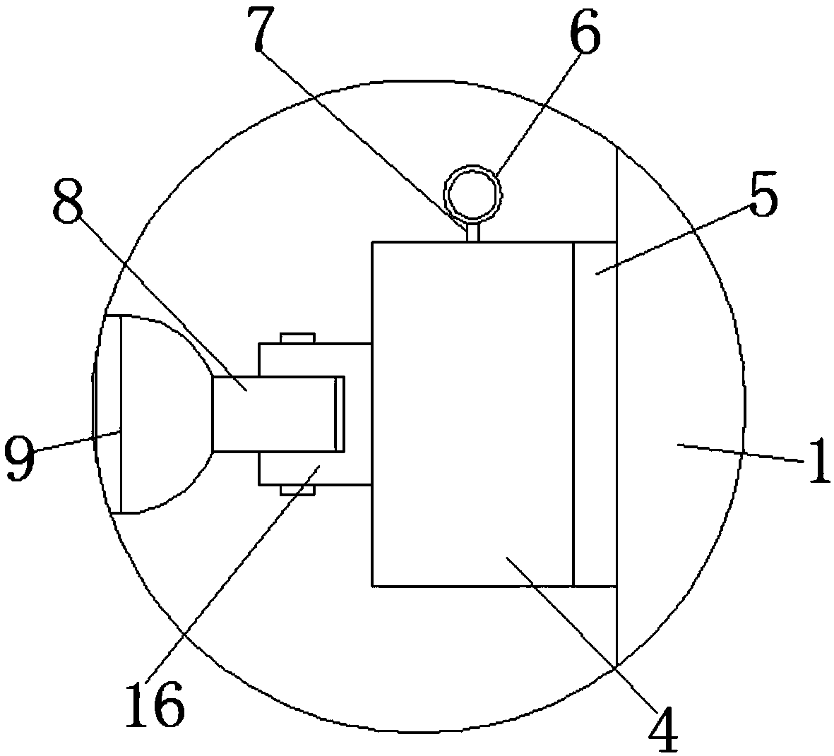
[0019] see Figure 1-5 , a control cabinet for printing and dyeing equipment, comprising a cabinet body 1, a cabinet door 2 is movably connected to the right side of the front surface of the cabinet body 1 through a hinge, and a mounting plate 5 is fixedly connected to the right side of the inner cavity of the cabinet door 2, and the mounting plate 5 The left side of the rotating shell 4 is provided with a rotating shell 4, the inner cavity of the rotating she...


PUM


Abstract

The invention discloses a control cabinet for printing equipment. The control cabinet comprises a cabinet body, a cabinet door is movably connected to the right side of the front surface of the cabinet body through hinges, a mounting plate is fixedly connected to the right side of an inner cavity of the cabinet door, a rotary shell is arranged at the left side of the mounting plate, a fixed blockis arranged at an inner cavity of the rotary shell, a locating groove is formed in the surface of the fixed block, a connecting plate is arranged at the top of the fixed block, a locating block whichis used in cooperation with the locating groove is fixedly connected to the bottom of the connecting plate, and a telescopic rod is fixedly connected to the top of the connecting plate. By means of the control cabinet for the printing equipment, through the cooperative use of the cabinet body, the cabinet door, supporting legs, the rotary shell, the mounting plate, a pulling ring, the telescopic rod, a connecting plate, an illumination lamp, a locating block, a fixed block, locating grooves, a circular plate, the connecting plate, a spring and a mounting shelf, the problem that the control cabinet for the printing equipment is inconveniently used by a user is solved; the control cabinet has the advantage of being conveniently used by the user.

Description

technical field [0001] The invention relates to the technical field of printing and dyeing equipment, in particular to a control cabinet for printing and dyeing equipment. Background technique [0002] Printing and dyeing, also known as dyeing and finishing, is a processing method and a general term for pretreatment, dyeing, printing, finishing, washing, etc. [0003] The control cabinet is an important component of the printing and dyeing equipment. It is necessary to install more control components inside the control cabinet. Therefore, the user needs to regularly maintain the components inside the control cabinet. Because the light inside the control cabinet is dark, use The user needs to illuminate its interior with the help of a lighting lamp, and the interior of the existing control cabinet for printing and dyeing equipment does not have the function of a lighting lamp, so the user needs to hold the lighting lamp with one hand, and use the other hand to illuminate the ...

Claims


Application Information

Patent Timeline
IPC IPC(8): D06B23/00
CPCD06B23/00
Inventor 叶侃
Owner 叶侃
Why Eureka
Try Eureka