Lifting working platform with self-locking mechanism

A workbench and self-locking technology, which is applied in the direction of building structure, house structure support, house structure support, etc., can solve the problems of inconvenient adjustment of the work platform, troubles, etc., achieve self-locking fast and convenient, easy to use, and prevent slide rails from sliding down Effect

Pending Publication Date: 2018-08-03
开平天盛卓越机械设备有限公司
View PDF0 Cites 2 Cited by
  • Summary
  • Abstract
  • Description
  • Claims
  • Application Information

AI Technical Summary

Problems solved by technology

However, it is cumbersome to use the locking bolt to pass through the jack and the locking hole to fix the work platform, and it is necessary for the staff to check with the naked eye whether the jack on the slide rail is aligned with the lock on the mast during the lifting process of the slide rail. Tight hole, when the jack is aligned with the locking hole, stop the lifting of the slide rail, and then manually use the pin to pass through the jack hole and the locking hole, which is not convenient for the staff to adjust the height of the working platform

Method used


Image

  • Lifting working platform with self-locking mechanism
  • Lifting working platform with self-locking mechanism
  • Lifting working platform with self-locking mechanism

Examples


Embodiment Construction

[0027] In describing the present invention, it is to be understood that the terms "length", "upper", "lower", "front", "rear", "left", "right", "vertical", "horizontal", The orientation or positional relationship indicated by "top", "bottom", etc. are based on the orientation or positional relationship shown in the drawings, and are only for the convenience of describing the present invention and simplifying the description, rather than indicating or implying that the referred device or element must have Certain orientations, constructed and operative in certain orientations, therefore are not to be construed as limitations on the invention.

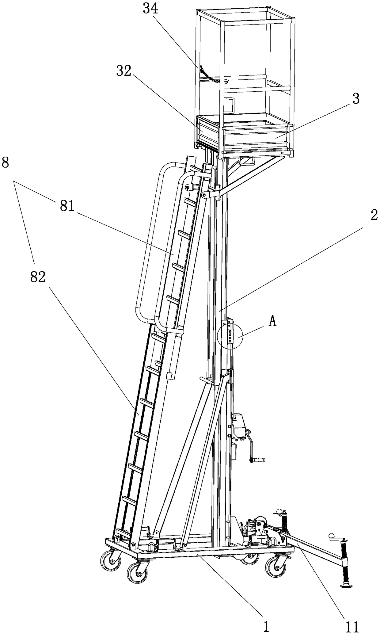
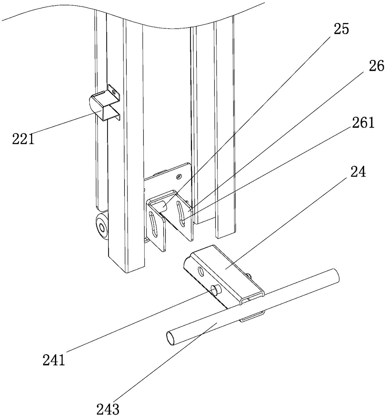
[0028] refer to Figure 1 to Figure 4 , a lifting workbench with a self-locking mechanism, including a chassis 1, a lifting mechanism 2, and a workbench 3, and the lifting mechanism 2 includes a lifting rail 21 connected to the chassis 1, and the lifting rail 21 slide rail 22 connected up and down, and the lifting device 23 that drives ...


PUM


Abstract

The invention discloses a lifting working platform with a self-locking mechanism. The lifting working platform comprises a bottom frame, a lifting mechanism and a working platform body. The lifting mechanism comprises a lifting rail, a sliding rail and a lifting device. Clamping holes are formed in the side, close to the sliding rail, of the lifting rail; inserting blocks with one ends being usedfor being inserted into the clamping holes are hinged to the sliding rail; a limiting device is arranged on the sliding rail; and the inserting blocks are matched with the lifting rail under the effect of the limiting device to support the sliding rail. Compared with the prior art, the lifting working platform is advantageous in that the inserting blocks are hinged to the sliding rail and automatically inserted into the clamping holes in the lifting rail in the lifting process of the sliding rail, and the swing ranges of the ends, inserted into the clamping holes, of the inserting blocks are limited by the limiting device so that during height adjustment of the working platform body, the lifting mechanism can be automatically locked in the way that the inserting blocks are inserted into the clamping holes through, the sliding rail is prevented from downwards sliding, the safety of the working platform body is guaranteed, the steps of manual hole calibration and inserting of locking plugs into locking holes and inserting holes are omitted, thus lifting of the lifting mechanism is quicker and more convenient, and using by construction personnel is facilitated.

Description

technical field [0001] The invention belongs to the technical field of aerial work platforms, and in particular relates to a lifting work platform with a self-locking mechanism. Background technique [0002] People often use elevating work platforms when carrying out high-altitude operations. The elevating work platforms can adjust the height of the work platform and are used to send people to suitable positions for high-altitude operations. At present, an existing lifting operation platform is composed of a supporting base, a telescopic supporting frame and a working platform. The telescopic supporting frame includes a mast arranged on the supporting Rail and bolt locking device, the working platform is set on the top of the slide rail, and the working platform slides up and down with the sliding rail to adjust the height of the working platform. The bolt locking device includes locking bolts and multiple locks set on the mast. The tight hole and the socket set on the slid...

Claims


Application Information

Patent Timeline
Patent Type & Authority Applications(China)
IPC IPC(8): E04G1/15E04G1/18E04G1/24
CPCE04G1/152E04G1/18E04G1/24E04G2001/246E04G2001/248
Inventor 冯瑞华
Owner 开平天盛卓越机械设备有限公司
Why Eureka
Try Eureka