High narrow large orifice intake gate water draining method and device

A technology for water intake gates and orifices, which is applied in water conservancy projects, sea area projects, coastline protection, etc., can solve the problems of increasing the uneconomical opening and closing capacity and increasing project investment, so as to reduce the opening force, save investment, The effect of increasing the exhaust velocity

Active Publication Date: 2018-07-27
CHINA POWER CONSRTUCTION GRP GUIYANG SURVEY & DESIGN INST CO LTD
View PDF7 Cites 0 Cited by
  • Summary
  • Abstract
  • Description
  • Claims
  • Application Information

AI Technical Summary

Problems solved by technology

However, for high, narrow and large orifice inlet gates, the water head from the water inlet of the filling valve to the bottom sill of the inlet gate is relatively high, and some projects reach 20m, which has greatly exceeded the opening force of the normal operation of the inlet gate, and the hoist needs to be increased Capacity can only open the door, which will increase the project investment, especially for hydropower projects with multiple ports, and the probability of this kind of working condition in normal operation is very small, so increase the opening and closing capacity for an unconventional operating condition Then it seems very uneconomical, so there are still deficiencies in the prior art and need to be further improved

Method used


Image

  • High narrow large orifice intake gate water draining method and device
  • High narrow large orifice intake gate water draining method and device
  • High narrow large orifice intake gate water draining method and device

Examples


Embodiment

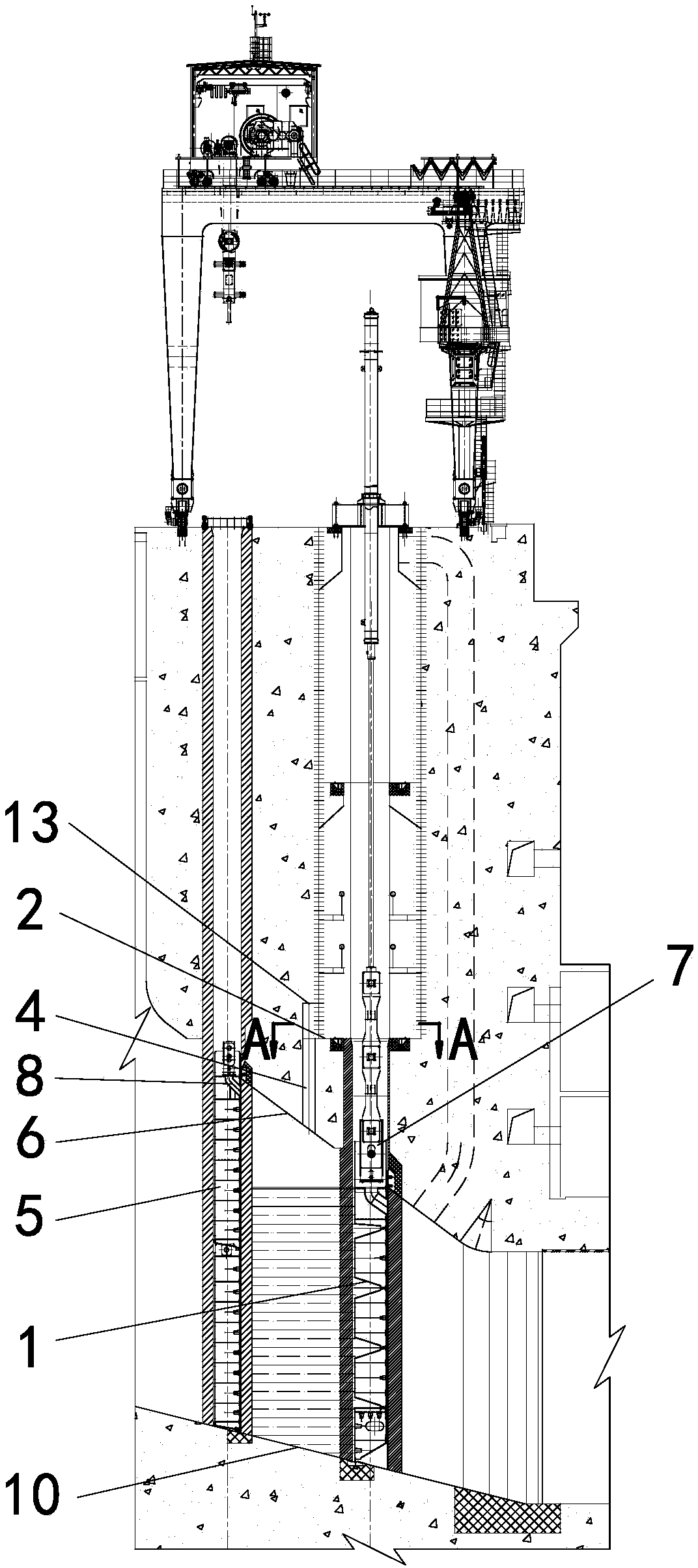
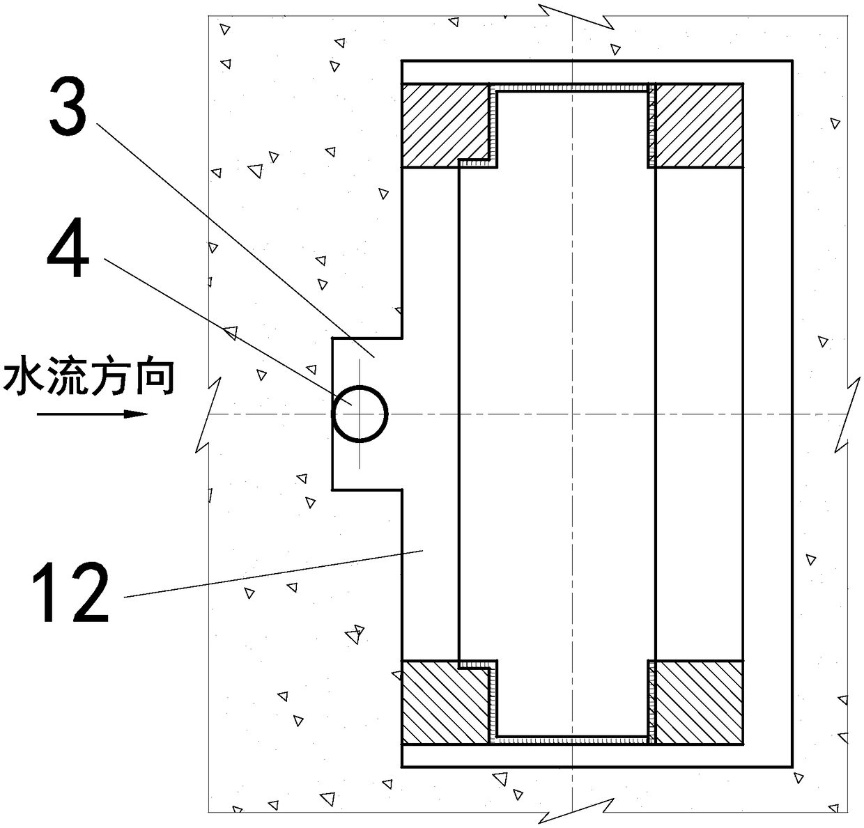
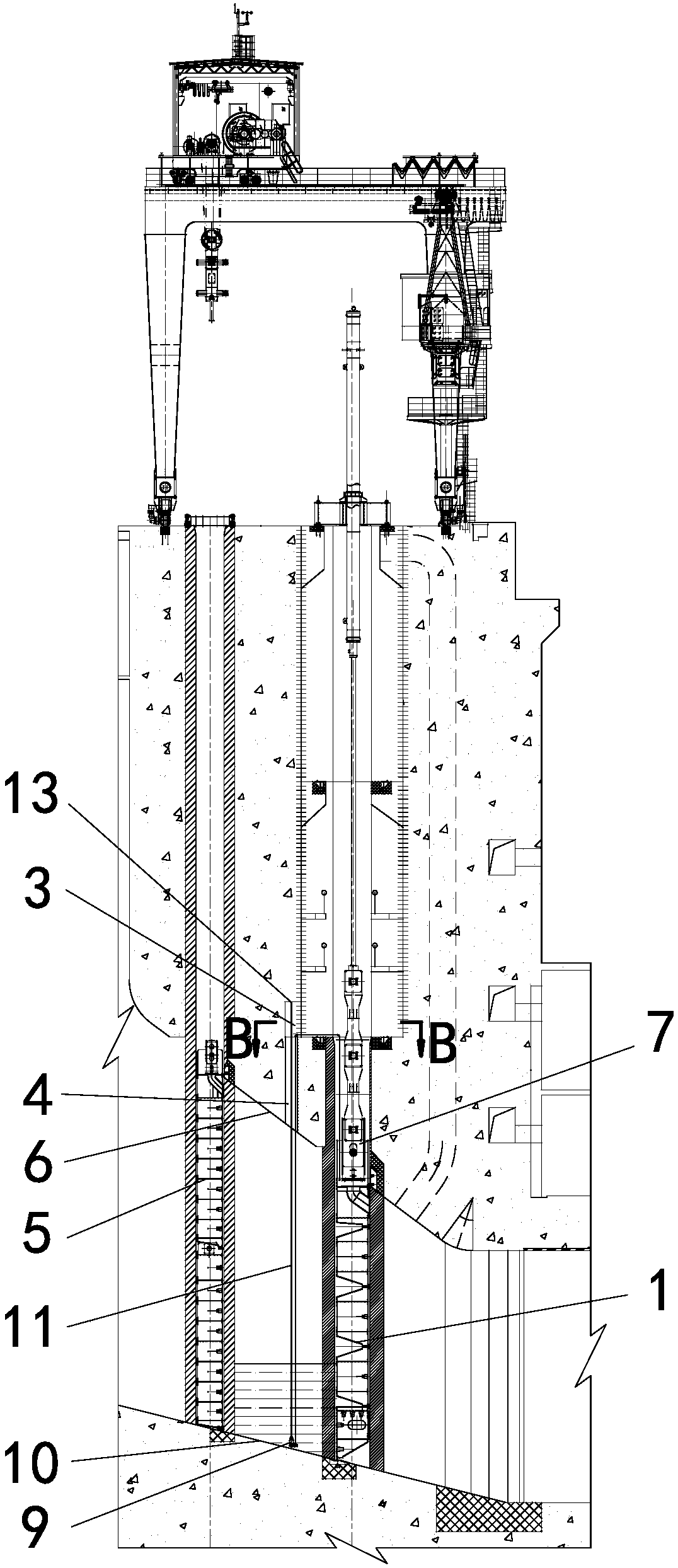
[0023] Examples of the present invention are Figure 1~4 As shown, a rectangular groove 3 is opened in the middle of the upstream side of the maintenance platform 2 of the water inlet gate 1, and a circular hole 4 is set at the lower part of the rectangular groove 3 to lead to the flow channel between the lower maintenance gate 5 and the water inlet gate 1. Top 6. When the water inlet gate 1 utilizes its top water filling valve 7 to discharge water to the water inlet of the water filling valve 7, the temporary submersible pump 9 is placed on the bottom sill 10 between the maintenance gate 5 and the water inlet gate 1 through the circular hole 4, Use the temporary submersible pump 9 to pump the remaining water between the maintenance gate 5 and the water inlet gate 1 to the water inlet of the water filling valve 7 of the water inlet gate 1, and discharge the water to the dam body through the water outlet of the water filling valve 7 of the water inlet gate 1 Downstream; the re...


PUM


Abstract

The invention discloses a high narrow large orifice intake gate water draining method and device. According to the method and device, a rectangular groove is formed in the middle of the upstream sideof the maintenance platform of an intake gate; a circular hole is formed in the bottom of the rectangular groove and communicates with the top of a passageway between a maintenance gate and the intakegate; when the intake gate utilizes a filling valve at the top of the intake gate to drain water to the water inlet of the filling valve, a temporary submersible pump is placed on a bottom sill between the maintenance gate and the intake gate through the circular hole; the temporary submersible pump pumps the rest water between the maintenance gate and the intake gate to the water inlet of the filling valve of the intake gate; and the water is drained to the downstream of a dam body through the water outlet of the filling valve of the intake gate, so that the water pressure born by the intakegate is lowered to reduce the lifting power for door, the requirement that the hoist capacity under normal operation opens the intake gate is met, and the hoist capacity of the intake gate is not needed to be improved to reduce the investment cost of the intake gate.

Description

technical field [0001] The invention relates to a drainage method and device for a high-narrow-large-orifice intake gate, which belongs to the technical field of metal structures of water conservancy and hydropower projects. Background technique [0002] For the quick gate of the water inlet or the emergency gate of the water inlet of the axial flow unit (hereinafter referred to as the water inlet gate), the layout plan of one door and one machine is usually adopted, and the maintenance gate is generally set in front of the water inlet gate in consideration of the maintenance needs of the water inlet gate. During the construction period or maintenance period, considering the needs of the water retaining installation or maintenance unit, the water inlet gate is in the closed water retaining state. The water inlet gate in the closed state cannot achieve water filling pressure. In the prior art, the maintenance gate is generally lowered to close the water retaining, and the wa...

Claims


Application Information

Patent Timeline
Patent Type & Authority Applications(China)
IPC IPC(8): E02B7/20E02B7/26E02B7/36
CPCE02B7/20E02B7/26E02B7/36Y02E10/20
Inventor 王兴恩
Owner CHINA POWER CONSRTUCTION GRP GUIYANG SURVEY & DESIGN INST CO LTD
Why Eureka
Try Eureka