A broadband continuous terahertz radiation source and corresponding excitation method

A terahertz radiation source and wide-band technology, applied in the field of terahertz waves, can solve problems such as not fully suitable for microwave theory, shortened life, decreased output power and work efficiency, etc.

Active Publication Date: 2019-10-01
成都清大华科微晶材料有限责任公司
View PDF17 Cites 0 Cited by
  • Summary
  • Abstract
  • Description
  • Claims
  • Application Information

AI Technical Summary

Problems solved by technology

[0005] The infrared technology and microwave technology on both sides of the terahertz radiation band are very mature, but the terahertz technology is still far from perfect. The reason is that this wave band is neither completely suitable for processing by optical theory nor microwave theory. To study, and the wavelength range from 0.03mm to 3mm, as far as the current situation is concerned, the range is too large, and in the field of terahertz waves, it is not clear which ranges of wavelengths in this wavelength range have special effects
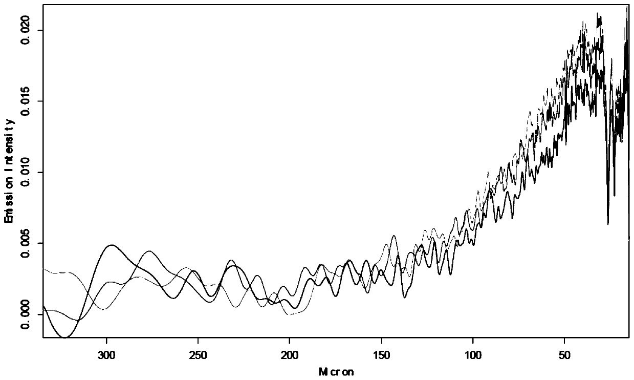
[0006] In view of the fact that certain diseases of the human body are closely related to terahertz waves, the applicant found that broadband continuous terahertz waves with all wavelengths in the range of 30u-1000u (at different times and at different temperatures, such terahertz waves have different characteristic wave state, and these wave states are all in the larger range of 30u-1000u, so as to define the "broadband", and these waves are continuous, so as to define the "continuous"), in medicine There are significant application effects, but unfortunately, there is no way to stably generate such broadband continuous terahertz waves
[0007] There are two types of traditional ways to generate terahertz waves. One is to use electronic methods to generate radiation sources. When the frequency of radiation sources generated by electronic methods exceeds 1T, the output power and work efficiency will drop sharply, and the lifespan will be shortened. The new structure is also hindered by micro The limit of processing technology; the second is to use optical methods to generate radiation sources. Although optical methods can obtain terahertz radiation with a wide spectrum range, they are bulky, expensive, and expensive, and their applications are limited.
[0008] These two methods currently have technical defects, and they cannot simultaneously and stably generate the continuous terahertz waves in the range of 30u-1000u that we need (the word "simultaneously" here means: what is produced is not a single beam, It is a continuous wave from 30u-1000u without breaks, with multiple peaks and troughs)

Method used


Image

  • A broadband continuous terahertz radiation source and corresponding excitation method
  • A broadband continuous terahertz radiation source and corresponding excitation method
  • A broadband continuous terahertz radiation source and corresponding excitation method

Examples


Embodiment 1

[0042] Such as Figure 2-5 , this embodiment discloses a broadband continuous terahertz radiation source, which includes:

[0043] Exciter 2;

[0044] A reflector 3, the reflector 3 is arranged on one side of the excitation body 2, in this embodiment, the reflector 3 is a metal film (the reflector 3 has a reflection function, not only limited to reflecting light energy, but also can reflect electric energy, thermal energy or terahertz waves, etc.), and the reflective surface (towards the excitation body 2) is configured as a plurality of protrusions 7 (the top view profile of a single protrusion 7 is a rectangle, such as Figure 5 , Figure 5 is a top view), the protrusions 7 are arranged in a rectangular array;

[0045] Crystal 1, the crystal is arranged on the side opposite to the reflector 3 of the excitation body 2 (the positional relationship after combination is as follows figure 1 , in the form of superposition, figure 2 It is a side-view exploded view, which is u...

Embodiment 2

[0055] Such as Image 6 , 7 The difference between this embodiment and Embodiment 1 is that the conductive copper strip 4 is arranged around the top of the insulating substrate 5, and a plurality of excitation strips 6 are arranged in a "well" structure, and both ends are connected to the conductive copper strip 4 Secondly, in this embodiment, the excitation belt 6 is other heating devices that do not include or not all include carbon fibers and graphene combined with carbon fibers, such as resistance wires, lasers, plasmas or photoelectric irradiation devices, as long as " After being excited, electric energy, heat energy, light energy or terahertz wave, or any combination of these four kinds of energy can be generated”; moreover, the reflector is a non-metal reflector, such as a mirror, which belongs to the non-metal reflector.

[0056] In this embodiment, the crystal is configured such that after being used in conjunction with the exciter 2 and the above-mentioned reflecto...

Embodiment 3

[0059] In this embodiment, the crystal is configured such that after being used in conjunction with the exciter 2 and the above-mentioned reflector 3, the outer surface of the crystal finally outputs terahertz waves with a wavelength in the range of 100u-150u and a continuous waveform without breaks. Wave.


PUM


Abstract

The present invention relates to the field of Terahertz waves, especially to a broadband and continuous Terahertz radiant source. The broadband and continuous Terahertz radiant source comprises: an excitation body; a reflection body arranged at one side of the excitation body; and a crystal arranged at one side, opposite to the reflection body, of the excitation body. The cooperation of the excitation body, the reflection body and the crystal meets the requirement that: energy is supplied to the excitation body to start the excitation body, Terahertz waves with wave lengths in a range of 30-1000[Mu] and with continuous and non-fracture waveforms are finally output from the outer surface of the crystal. The objective of the invention is to provide a Terahertz radiant source capable of generating broadband and continuous Terahertz waves with wave lengths in a range of 30-1000[Mu]. The present invention further discloses a method for generating the Terahertz waves.

Description

technical field [0001] The invention relates to the field of terahertz waves, in particular to a broadband continuous terahertz radiation source. Background technique [0002] THz wave (terahertz wave) or THz ray (terahertz ray) was officially named from the middle and late 1980s. Before that, scientists collectively referred to it as far-infrared ray. [0003] Terahertz waves refer to electromagnetic waves with a frequency in the range of 0.1THz to 10THz and a wavelength in the range of 0.03mm to 3mm, which is between the infrared band and the millimeter wave. [0004] From the perspective of radiation wavelength, its size is between electrons and photons, belonging to the transition zone from electronics to photonics, and in the transition zone from macroscopic classical theory to microscopic quantum theory. [0005] The infrared technology and microwave technology on both sides of the terahertz radiation band are very mature, but the terahertz technology is still far fro...

Claims


Application Information

Patent Timeline
Patent Type & Authority Patents(China)
IPC IPC(8): H01S1/02
Inventor 于川刘洪云于文学杨小誉
Owner 成都清大华科微晶材料有限责任公司
Why Eureka
Try Eureka