Learning mold of side surface unfolding pattern of cube and 90-degree rotation operation method thereof

A side unfolding and rotating operation technology, applied in the teaching field, can solve the problem that students are difficult to distinguish whether the unfolded figure is a cube unfolded figure, etc., and achieve the effect of flexible and changeable operation methods, low processing difficulty, and stable connection relationship

Inactive Publication Date: 2018-07-24
卢俊琪
View PDF6 Cites 0 Cited by
  • Summary
  • Abstract
  • Description
  • Claims
  • Application Information

AI Technical Summary

Problems solved by technology

[0003] The purpose of the present invention is to provide a learning mold for developing graphics on the side of a cube and its 90° rotation operation method, so as to solve the problem that in the junior high school learning stage, due to the variety of graphics after the cube is unfolded, students need to memorize them one by one, and it is difficult for students to distinguish them. Whether the expanded figure composed of six panels is a cube expanded figure

Method used


Image

  • Learning mold of side surface unfolding pattern of cube and 90-degree rotation operation method thereof
  • Learning mold of side surface unfolding pattern of cube and 90-degree rotation operation method thereof
  • Learning mold of side surface unfolding pattern of cube and 90-degree rotation operation method thereof

Examples


specific Embodiment approach 1

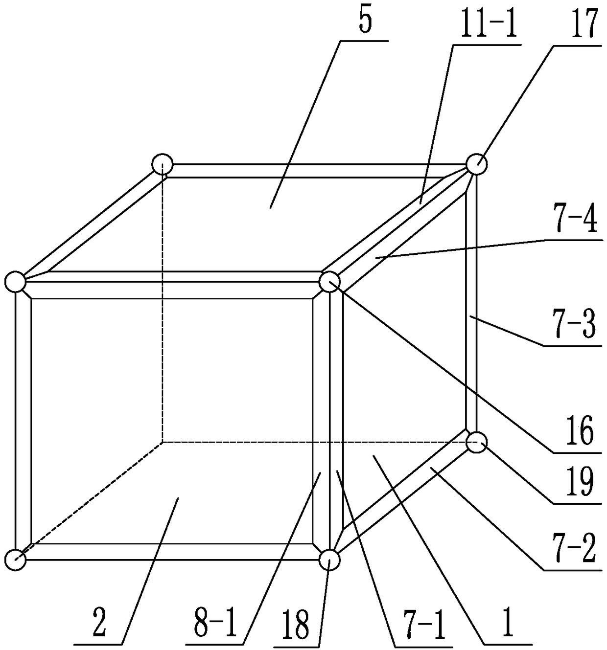
[0073] Specific implementation mode one: combine Figure 1 to Figure 16 Describe this embodiment, this embodiment includes the first composition panel 1, the second composition panel 2, the third composition panel 3, the fourth composition panel 4, the fifth composition panel 5 and the sixth composition panel 6, the first composition panel 1 , the second composition panel 2, the third composition panel 3, the fourth composition panel 4, the fifth composition panel 5 and the sixth composition panel 6 are all square plates, the first composition panel 1, the second composition panel 2, the third composition panel The composition panel 3 and the fourth composition panel 4 enclose in turn to form a square frame body, the fifth composition panel 5 is arranged on the top of the square frame body, and the surrounding edges of the fifth composition panel 5 are connected with the first composition panel 1 and the second composition panel respectively. The composition panel 2, the third...

specific Embodiment approach 2

[0078] Specific implementation mode two: combination Figure 8 , Figure 9-1 to Figure 13-2 To illustrate this embodiment, when the first component panel 1, the second component panel 2, the third component panel 3, the fourth component panel 4, the fifth component panel 5, and the sixth component panel 6 are on the same plane to form the basic figure, the A composition panel 1, a second composition panel 2, a third composition panel 3 and a fourth composition panel 4 are arranged in sequence to form a strip plate, and the fifth composition panel 5 and the sixth composition panel 6 are arranged on two sides of the first composition panel 1 respectively. side.

[0079] The basic figure is the basis of other side views of the cube. The structure of the basic figure and the setting position and connection relationship between each component panel are the best structures obtained through multiple sample tests.

specific Embodiment approach 3

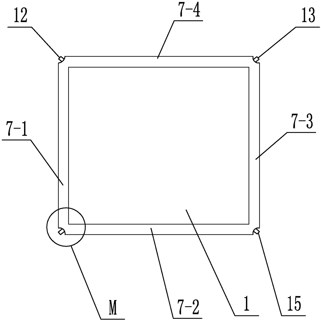
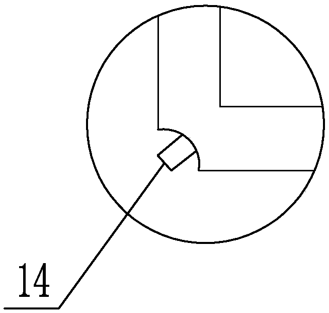
[0080] Specific implementation mode three: combination Figure 1 to Figure 16 To illustrate this embodiment, a first magnetic strip 7-1, a second magnetic strip 7-2, a third magnetic strip 7-3, and a fourth magnetic strip 7-4 are arranged on the peripheral edges of the first component panel 1, respectively. The second component panel 2 is provided with a fifth magnetic strip 8-1 at one end close to the first component panel 1, and the second component panel 2 connects with the first magnetic strip 7-1 of the first component panel 1 through the fifth magnetic strip 8-1. 1 Magnetic connection; the sixth component panel 6 is provided with a sixth magnetic strip near the end of the first component panel 1, and the sixth component panel 6 is connected to the second magnetic strip 7-2 of the first component panel 1 through the sixth magnetic strip Magnetic connection; the fourth component panel 4 is provided with a seventh magnetic strip near the end of the first component panel 1, ...


PUM


Abstract

The invention discloses a learning mold of a side surface unfolding pattern of a cube and a 90-degree rotation operation method thereof, and relates to a learning mold and an operation method thereof.In the learning stage of the junior middle school, there are various patterns after the cube is unfolded, the patterns need to be mechanically memorized by students one by one, it is difficult to thestudents to distinguish whether an unfolded pattern formed by six panels is a side surface unfolding pattern of the cube or not. In the invention, a first constitution panel, a second constitution panel, a third constitution panel and a fourth constitution panel form a square frame in an enclosing manner, a fifth constitution panel is arranged at the top end of the square frame, a sixth constitution panel is arranged at the bottom end of the square frame, and the six constitution panels are connected in a detachable manner. According to the method, one, two, three or four constitution panelsare selected from the unfolded pattern formed by the six constitution panels to serve as an overall rotation structure, and the left constitution panels serve as a fixed structure; whether there is anincluded angle of 90 degrees between the overall rotation structure and the fixed structure or not is judged, and if so, the overall rotation structure rotates by 90 degrees. The learning mold is used for assisting teaching or learning.

Description

technical field [0001] The invention relates to a learning mold and an operation method thereof, belonging to the technical field of teaching. Background technique [0002] At present, for the junior high school stage, there is relevant knowledge about the unfolded figures on the side of the cube. The existing teaching methods often list all the unfolded figures one by one, so that students can memorize them by rote, and some use formulas, so that not only must they memorize the formulas, You also need to understand the formulas, and you have to apply the formulas when using them. It is very inflexible to use, not only time-consuming but also brain-intensive, and it is easy to make mistakes. Contents of the invention [0003] The object of the present invention is to provide a learning mold for developing graphics on the side of a cube and its 90° rotation operation method to solve the problem that in the junior high school learning stage, due to the variety of graphics af...

Claims


Application Information

Patent Timeline
Patent Type & Authority Applications(China)
IPC IPC(8): G09B23/04
CPCG09B23/04
Inventor 卢俊琪张文静王丰卢伟
Owner 卢俊琪
Why Eureka
Try Eureka