
A rapid drying device and a control method

A technology of fast drying and drying device, applied in the field of clothes dryers, can solve the problems of increasing the thickness of clothes in the middle, different lengths of clothes, and difficulty in drying clothes, etc., and achieves the effect of preventing clothes from slipping.

Inactive Publication Date: 2018-07-10
QINGDAO HAIER WASHING MASCH CO LTD
View PDF7 Cites 3 Cited by
  • Summary
  • Abstract
  • Description
  • Claims
  • Application Information

AI Technical Summary

Problems solved by technology

However, because the clothes are of different lengths, fat and thin, especially men's clothes and women's clothes are very different in size, in order to improve the versatility of the clothes dryer, it is necessary to equip the clothes dryer with multiple airbags of different models. Replace it according to the need when using it, which will increase the cost of the dryer and increase the price, and the airbag will be easily damaged after repeated replacement, making it inconvenient to use
[0004] Patent CN201120484691 provides an airbag, including an airbag and an air inlet. The airbag body is made of a breathable material. The air inlet is arranged on the airbag body. An adapter tube is arranged on the air inlet. The Velcro tape of the size of the capsule body, in this structure, the Velcro tape can only reduce the longitudinal length of the airbag, and the reduction of the lateral shoulder circumference is realized by the self-locking nylon drawstring, and it can be seen from the attached drawings that the structure The main function of Zhongzhong Velcro and drawstring is to adjust the size of the airbag, which is suitable for different sizes of clothes. This conclusion can be obtained from Figure 1 and Figure three In addition, the adjustment of the length of the clothes in the picture is through Velcro, and the horizontal adjustment is only through the drawstring on the shoulder. The adjustment of this position is to make the airbag suitable for different sizes of clothing on the shoulder, but in the actual airbag use During the process, the part below the chest of the airbag usually has the same upper and lower circumference. When the clothes are put on the airbag for blowing and drying, the airbag is propped up. Because the expansion coefficient of the part of the airbag that is not in contact with the edge of the clothes is large, it will cause A thrust pushes the clothes to gather in the middle, increasing the thickness of the clothes in the middle, making the clothes not easy to dry and affecting the drying speed

Method used


Image

  • A rapid drying device and a control method
  • A rapid drying device and a control method
  • A rapid drying device and a control method

Examples


Embodiment 1

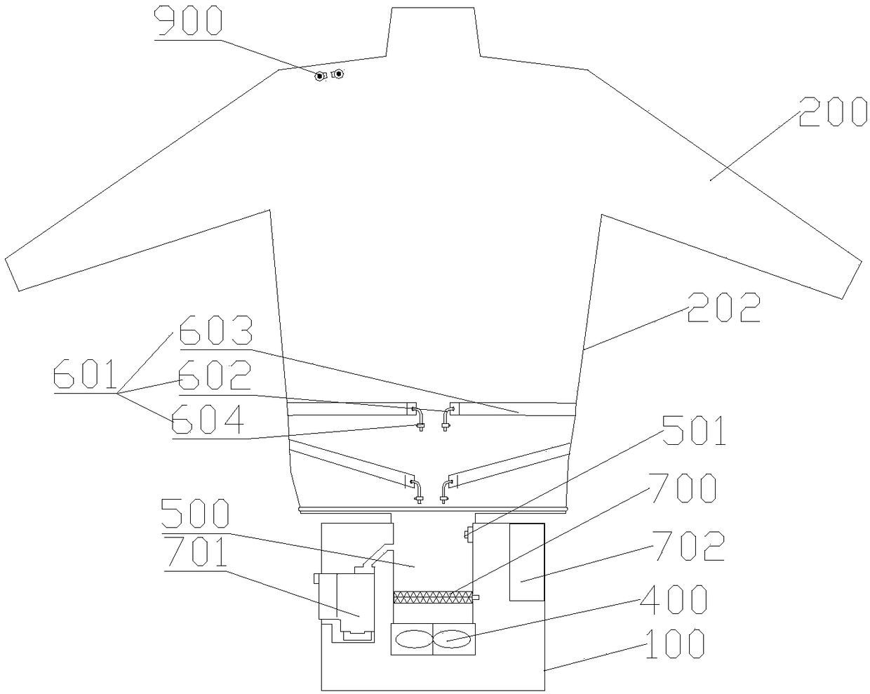
[0050] Such as Figure 1-3 As shown, a quick drying device includes a base 100, an air bag 200 arranged on the base 100 for covering clothes, and a drying device for blowing drying air into the air bag 200. The air bag 200 has a limited Position structure 202, the position-limiting structure 202 prevents the clothes from slipping after the airbag 200 is inflated.

[0051] Since the airbag 200 is soft, after the airbag 200 inflates, the inflation of the airbag exerts a force on the clothes, so that some parts of the clothes are unbalanced by the force of the airbag 200, and the clothes will slip. The sliding action tends to make the clothes pile up, which makes the part difficult to dry. Even if the part is dried for a long time, it will cause the part to form wrinkles; it can be artificially flattened during the drying process, but because the clothes The force on this part is still unbalanced, and slippage will occur.

[0052] By setting the limiting structure 202, the limi...

Embodiment 2

[0061] Such as Figure 1-3 As shown, the present embodiment is a further limitation to Embodiment 1, the airbag 200 is a jacket-shaped airbag 200, the airbag 200 is located below the chest, and the upper circumference of the airbag 200 is greater than the lower circumference.

[0062] Further, the circumference of the airbag 200 below the chest gradually increases from bottom to top, that is, the airbag 200 is in an inverted cone shape.

[0063] Such as figure 1 As shown, the shaded part in the figure is the clothing on the airbag. When the clothing is placed on the airbag 200, the circumference of the airbag 200 below the lower edge of the clothing is smaller than the circumference of the upper airbag 200 adjacent to it. When the airbag After 200 is inflated, the lower part of the clothing fits with the airbag 200, and the airbag 200 located below the lower edge of the clothing produces a relatively small upward component force on the clothing, and the friction force of the...

Embodiment 3

[0072] Such as image 3 As shown, on the basis of Embodiment 1 and Embodiment 2, the airbag 200 of this embodiment also includes a scaling member 601, and the scaling member 601 can shrink the airbag 200 inwardly so that the circumference of its adjacent part is larger than that of this part. The circumference forms a limiting structure 202 .

[0073] By setting the scaling member 601 on the airbag 200, the purpose of partially shrinking the airbag 200 is realized, and the expansion force generated by the airbag 200 on the contracted part is reduced, and the expansion force exerted on the clothing by the adjacent uncontracted part is larger than that The shrinking part exerts a large expansion force on the clothes, and the adjacent non-shrinking parts form a limiting part to balance the clothes.

[0074] Further, the oblique setting of the contraction element has a better effect.

[0075] This method can be applied to the airbag 200 with the limit structure 202 already insta...


PUM


Abstract

The invention relates to the field of clothes dryers, in particular to a rapid drying device and a control method. The rapid drying device comprises a pedestal, an air bag arranged on the pedestal andused for sleeving clothes, and a drying device sending drying air into the air bag. The air bag has a limiting structure which can prevent clothes from sliding after the air bag is inflated. Throughstructural design, clothes are not liable to slide relative to the air bag after the air bag swells, so that the problem that the clothes drying speed is influenced by clothes piling is solved and folds of clothes caused by sliding and piling can be prevented.

Description

technical field [0001] The invention belongs to the field of clothes dryers, and in particular relates to a quick drying device and a control method. Background technique [0002] Nowadays, the pace of people's social life is very fast, and sometimes it is necessary to quickly dry the clothes, so that they can be washed and worn immediately, and at the same time avoid wrinkles on the clothes, which will affect the appearance; with the improvement of material and cultural living standards, people have more and more aesthetic requirements for clothes. The taller you are, the more everyone wants to wear comfortable, well-fitting clothes that fully reflect your appearance. It is very important to remove the wrinkles on the clothes. You can iron the clothes to make the clothes straight and reduce the wrinkles. [0003] At present, there is an air bag type clothes dryer in clothes dryers. When in use, clothes to be dried are put on the air bag, and hot air is blown into the air ba...

Claims


Application Information

Patent Timeline
IPC IPC(8): D06F59/02
CPCD06F59/02D06F73/00
Inventor 李以民劳春峰许升宋华诚
Owner QINGDAO HAIER WASHING MASCH CO LTD
Learn More