Road tamping device capable of being controlled automatically

A technology for compacting devices and roads, applied in the directions of roads, roads, road repair, etc., can solve the problems of increased transportation costs, high labor intensity, poor compaction effect, etc., to improve accuracy and stability, reduce labor intensity, and facilitate operation. Effect

Inactive Publication Date: 2018-06-29
杨田花
View PDF0 Cites 0 Cited by
  • Summary
  • Abstract
  • Description
  • Claims
  • Application Information

AI Technical Summary

Problems solved by technology

[0002] With the continuous development of the social economy and the continuous improvement of the construction level, it is often necessary to tamp the road subgrade and the road surface during road construction; at present, the tamping of the ground level and the subgrade is often done manually, but there is a need for manual tamping. The shortcomings of poor effect and low compacting efficiency; although some mechanized compacting machines have appeared on the market at present, such compacting machines need to manually grasp the forward direction of the compacting machine, so there is labor intensity and the direction of the compacting machine. The disadvantage of being difficult to control. In addition, if you move the compactor, you need to use external auxiliary machinery, which increases the cost of transportation and cannot be widely used in the field of compaction machinery.

Method used


Image

  • Road tamping device capable of being controlled automatically
  • Road tamping device capable of being controlled automatically
  • Road tamping device capable of being controlled automatically

Examples


Embodiment Construction

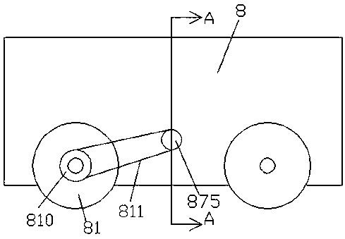
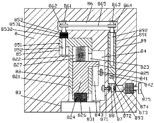
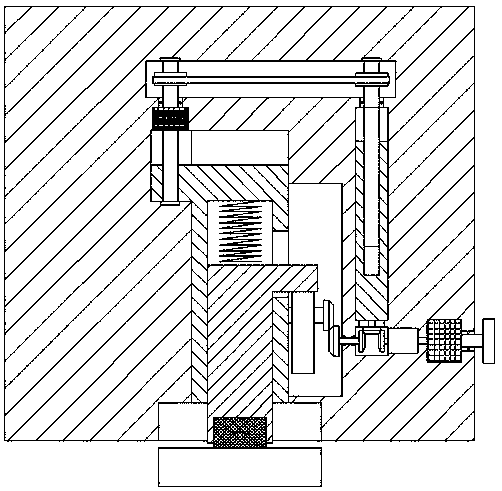
[0020] Such as Figure 1-Figure 4 As shown, an automatically controlled road tamping device of the present invention includes a tamping car body 8 and two sets of walking rollers 81 that are rotatably arranged at the bottom of the front and rear sides of the tamping car body 8, and the bottom end surface of the tamping car body 8 There is a sinking groove 83 inside, and the inner top wall of the sinking groove 83 is connected with a lifting sliding groove 82 extending upwards, and the inner wall of the compacted car body 8 above the lifting sliding groove 82 is provided with left and right extending The first transmission cavity 86, the inner wall of the right side of the lift sliding groove 82 is connected with the second transmission cavity 84, and the top of the left inner wall of the lifting and sliding groove 82 is connected with the first guide groove 85, and the second transmission cavity 85 is connected with the inner wall of the left side of the lifting slide groove 82...


PUM


Abstract

The invention discloses a road tamping device capable of being controlled automatically. The road tamping device capable of being controlled automatically comprises a tamping vehicle body and two setsof waking rollers rotatably arranged at the bottoms of the front and rear sides of the tamping vehicle body, a sunk groove is formed in the end surface of the bottom of the tamping vehicle body, anda lifting sliding groove extending upwards is formed in the inner top wall of the sunk groove in a communicating mode. A first transmission cavity extending to the left and right is formed in the position, located above the lifting sliding groove, in the inner wall body of the tamping vehicle body, a second transmission cavity is formed in the inner wall of the right side of the lifting sliding cavity in a communicating mode, and a first guide groove is formed in the top of the inner wall of the left side of the lifting sliding cavity in a communicating mode. The top of the first guide grooveis opposite to the bottom of the extending tail end of the left side of the first transmission cavity, a first threaded rod extending vertically is formed in the first guide groove, the extending tailend of the top of the first threaded rod is connected with a first motor in a matched mode, and the outer surface of the first motor is embedded into the inner top wall of the first guide groove andis fixedly connected with the first guide groove. The road tamping device capable of being controlled automatically is simple in structure and easy to operate, the precision and stability of tamping are improved, the labor intensity of workers is reduced, and the cost of transportation is reduced.

Description

technical field [0001] The invention relates to the technical field of road construction, in particular to an automatically controlled road compacting device. Background technique [0002] With the continuous development of the social economy and the continuous improvement of the construction level, it is often necessary to tamp the road subgrade and the road surface during road construction; at present, the tamping of the ground level and the subgrade is often done manually, but there is a need for manual tamping. The shortcomings of poor effect and low compacting efficiency; although some mechanized compacting machines have appeared on the market at present, such compacting machines need to manually grasp the forward direction of the compacting machine, so there is labor intensity and the direction of the compacting machine. The disadvantage of being difficult to control. In addition, if the tamping machine is moved, it needs to use external auxiliary machinery, which incr...

Claims


Application Information

Patent Timeline
Patent Type & Authority Applications(China)
IPC IPC(8): E01C19/34
CPCE01C19/34
Inventor 杨田花
Owner 杨田花
Why Eureka
Try Eureka