
Multi-axis mechanical arm with electric clamping claw

A technology of manipulators and grippers, applied in the field of multi-axis manipulators, which can solve problems such as changes in motion coordinates, unfavorable repetitive positioning of robots, and impacts

Active Publication Date: 2018-06-15
华南智能机器人创新研究院 +1
View PDF6 Cites 2 Cited by
  • Summary
  • Abstract
  • Description
  • Claims
  • Application Information

AI Technical Summary

Problems solved by technology

In common articulated robots, the driving components of each arm are installed on the joints connected to the forearm. As the number of arms increases, the load on each arm will increase accordingly, resulting in an increase in the volume of the driving power components of the arm and an increase in the movement speed of the arm. Problems such as slowing down and reducing the accuracy of the arm are not conducive to the high-speed and miniaturization of joint robots
[0003] It is common to use robots for clamping operations in robot applications. Common clamping tools use air pressure as the driving force. When the clamping tool starts or stops, it will generate a large impact force, which is easy to cause damage to high-speed robots with small loads. The impact makes its motion coordinates change, which is not conducive to the repeated positioning of the robot; some clamping tools are also driven by motors, but the motor and clamping tools are often integrated, and the weight is heavy, which is not conducive to the high-speed movement of the robot

Method used


Image

  • Multi-axis mechanical arm with electric clamping claw
  • Multi-axis mechanical arm with electric clamping claw
  • Multi-axis mechanical arm with electric clamping claw

Examples


Embodiment Construction

[0066] The following will clearly and completely describe the technical solutions in the embodiments of the present invention with reference to the accompanying drawings in the embodiments of the present invention. Obviously, the described embodiments are only some, not all, embodiments of the present invention. Based on the embodiments of the present invention, all other embodiments obtained by persons of ordinary skill in the art without creative efforts fall within the protection scope of the present invention.

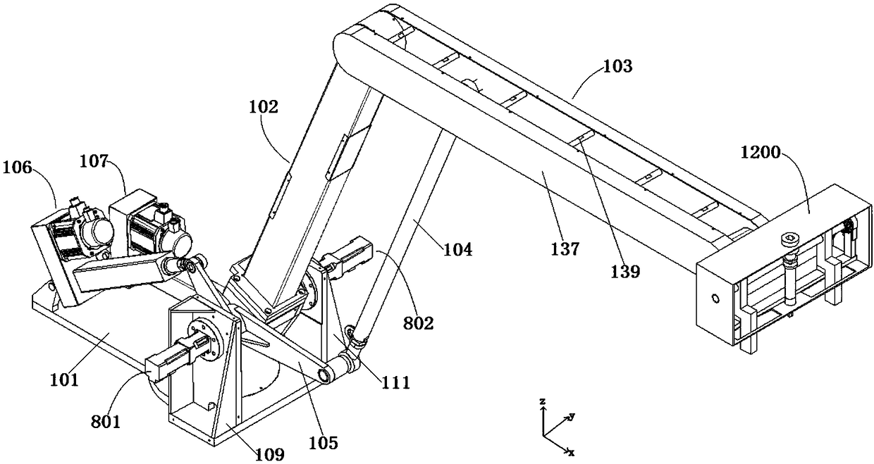
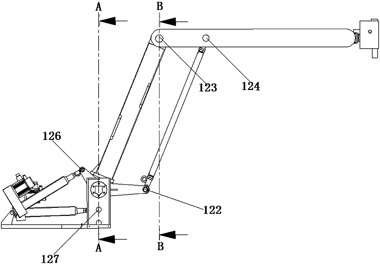
[0067] figure 1 It shows a schematic diagram of the three-dimensional structure of the multi-axis mechanical arm with electric grippers according to the embodiment of the present invention, figure 2 shows the front view of the multi-axis robotic arm with electric gripper according to the embodiment of the present invention, Figure 5 It shows the top view of the multi-axis mechanical arm of the electric gripper of the embodiment of the present invention. In order...


PUM


Abstract

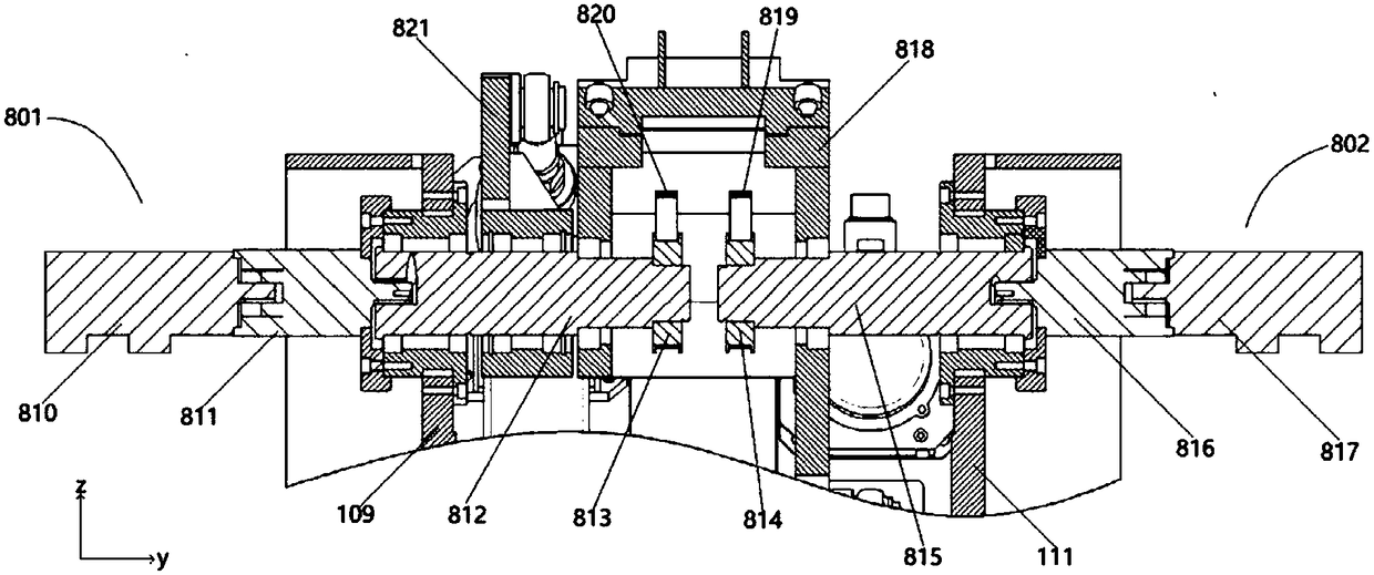
The invention provides a multi-axis mechanical arm with an electric clamping claw. A drive element is arranged on a platform at the bottom; a first arm and a second arm have no extra weight except respective weights and the weight of matched connection rods, and have the characteristic of high tail end moving speed and the like; the tail end of the second arm is provided with a working tail end capable of revolving and rotating, a higher degree of freedom of movement is achieved, and the operating requirements of different aspects can be met; a drive assembly for revolving and rotating of theworking tail end is also installed on the platform, the weight of the moving portion of the drive assembly is lower compared with an existing mechanical arm module, and the drive assembly is particularly suitable for quick movement operation of the working tail end; a drive component of the electric clamping claw is arranged outside a clamping claw body, so that loads of the second arm are furtherrelieved; and the clamping claw body achieves the actions of clamping and screwing with a small size, and great practicability is achieved.

Description

technical field [0001] The invention relates to the technical field of robots, in particular to a multi-axis mechanical arm with electric grippers. Background technique [0002] Robots can be divided into parallel robots and serial robots. Among them, the common type of serial robots is articulated robots. In common articulated robots, the driving components of each arm are installed on the joints connected to the forearm. As the number of arms increases, the load on each arm will increase accordingly, resulting in an increase in the volume of the driving power components of the arm and an increase in the movement speed of the arm. Problems such as slowing down and reducing the accuracy of the arm are not conducive to the high-speed and miniaturization of joint robots. [0003] It is common to use robots for clamping operations in robot applications. Common clamping tools use air pressure as the driving force. When the clamping tool starts or stops, it will generate a large...

Claims


Application Information

Patent Timeline
IPC IPC(8): B25J15/08B25J18/00B23P19/06
CPCB23P19/06B25J15/08B25J18/00
Inventor 谭军民周磊曹永军梁佳楠
Owner 华南智能机器人创新研究院
Learn More