
Cutting bed with cutting knife disk positioning device

A technology of positioning device and cutter head, applied in the field of cutting machine, can solve the problems of thickness, speed, precision deviation, easy displacement, small friction, etc., and achieve the effect of improving precision, improving efficiency and improving cutting speed.

Active Publication Date: 2018-06-12
YYC IND CO LTD CHINA
View PDF6 Cites 1 Cited by
  • Summary
  • Abstract
  • Description
  • Claims
  • Application Information

AI Technical Summary

Problems solved by technology

Especially for smooth fabrics, because of its small friction, it is easier to generate displacement, which will cause great deviations in the thickness, speed and accuracy of cutting.

Method used


Image

  • Cutting bed with cutting knife disk positioning device
  • Cutting bed with cutting knife disk positioning device
  • Cutting bed with cutting knife disk positioning device

Examples


Embodiment Construction

[0024] The embodiments of the present invention will be described in detail below with reference to the accompanying drawings, but the present invention can be implemented in many different ways defined and covered by the claims.

[0025] Embodiments of the present invention will be described in detail below in conjunction with the accompanying drawings.

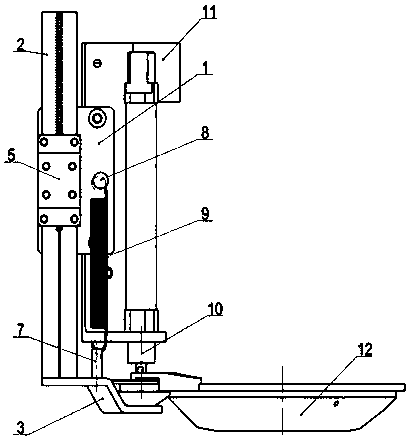
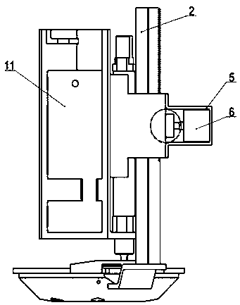
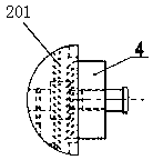
[0026] figure 1 A schematic structural diagram showing an embodiment of the present invention; figure 2 A schematic diagram showing another side structure of an embodiment of the present invention; image 3 A schematic diagram of the meshing structure of the gear block and the rack of the positioning shaft is shown. Such as Figure 1-Figure 3 As shown, the present invention provides a cutting bed with a cutter head positioning device, the cutting machine head frame base 11 is equipped with a fixing seat for the cutter head positioning device, and the fixing seat 1 is provided with a hollow channel , the positioning shaf...


PUM


Abstract

The invention discloses a cutting bed with a cutting knife disk positioning device. A fixing seat of the cutting knife disk positioning device is arranged on a clipping machine head rack base of the cutting bed, the fixing seat is provided with a hollow channel, a positioning shaft penetrates through the channel of the fixing seat, the bottom of the positioning shaft is connected with a supportingplate, a saw tooth fixing strip is arranged on a side surface of the positioning shaft and is fixed to a toothed block in an engaged manner, the toothed block is mounted on an outputting shaft of a cylinder, the cylinder is mounted on the fixing seat of the positioning device through a cylinder seat, a knife disk assembly is placed on the supporting plate, the supporting plate supports the knifedisk assembly, and when the knife disk assembly moves back and forth, the bottom of the knife disk assembly is not in contact with a fabric. The cutting bed with the cutting knife disk positioning device has the advantages that the cutting disk assembly is supported, the problem of position running of smooth fabrics is solved, the precision and efficiency are improved, and the clipping speed is increased.

Description

technical field [0001] The invention relates to the technical field of a cutting bed, in particular to a cutting bed with a cutter disc positioning device. Background technique [0002] The cutter head assembly of the cutting bed is a metal part, which is heavy and easy to sag. During the reciprocating cutting movement of the cutter head assembly, the bottom of the cutter head assembly will directly contact the fabric, and there is a thrust on the fabric. Especially for smooth fabrics, because of its small friction force, displacement is more likely to occur, which will cause great deviations in the thickness, speed and accuracy of cutting. This is where this application needs to focus on improvement. Contents of the invention [0003] The technical problem to be solved by the present invention is to provide a cutting bed with a cutter head positioning device with high cutting precision, fast speed and high efficiency. [0004] In order to solve the above technical probl...

Claims


Application Information

Patent Timeline
Patent Type & Authority Applications(China)
IPC IPC(8): D06H7/00
CPCD06H7/00
Inventor 徐小林
Owner YYC IND CO LTD CHINA
Learn More