
Adaptive control cabinet

An adaptive control cabinet technology, applied in the direction of cooling/ventilation/heating transformation, using gaseous coolant for modification, etc., can solve the problems that ordinary control cabinets cannot judge heat dissipation by themselves, so as to improve heat dissipation efficiency, save energy, enhance The effect of cooling effect

Inactive Publication Date: 2019-06-28
滁州伏特威电气技术有限公司
View PDF6 Cites 1 Cited by
  • Summary
  • Abstract
  • Description
  • Claims
  • Application Information

AI Technical Summary

Problems solved by technology

[0003] The present invention intends to provide an adaptive control cabinet to solve the problem that ordinary control cabinets cannot self-judge and control heat dissipation

Method used


Image

  • Adaptive control cabinet
  • Adaptive control cabinet

Examples


Embodiment Construction

[0015] Further detailed explanation through specific implementation mode below:

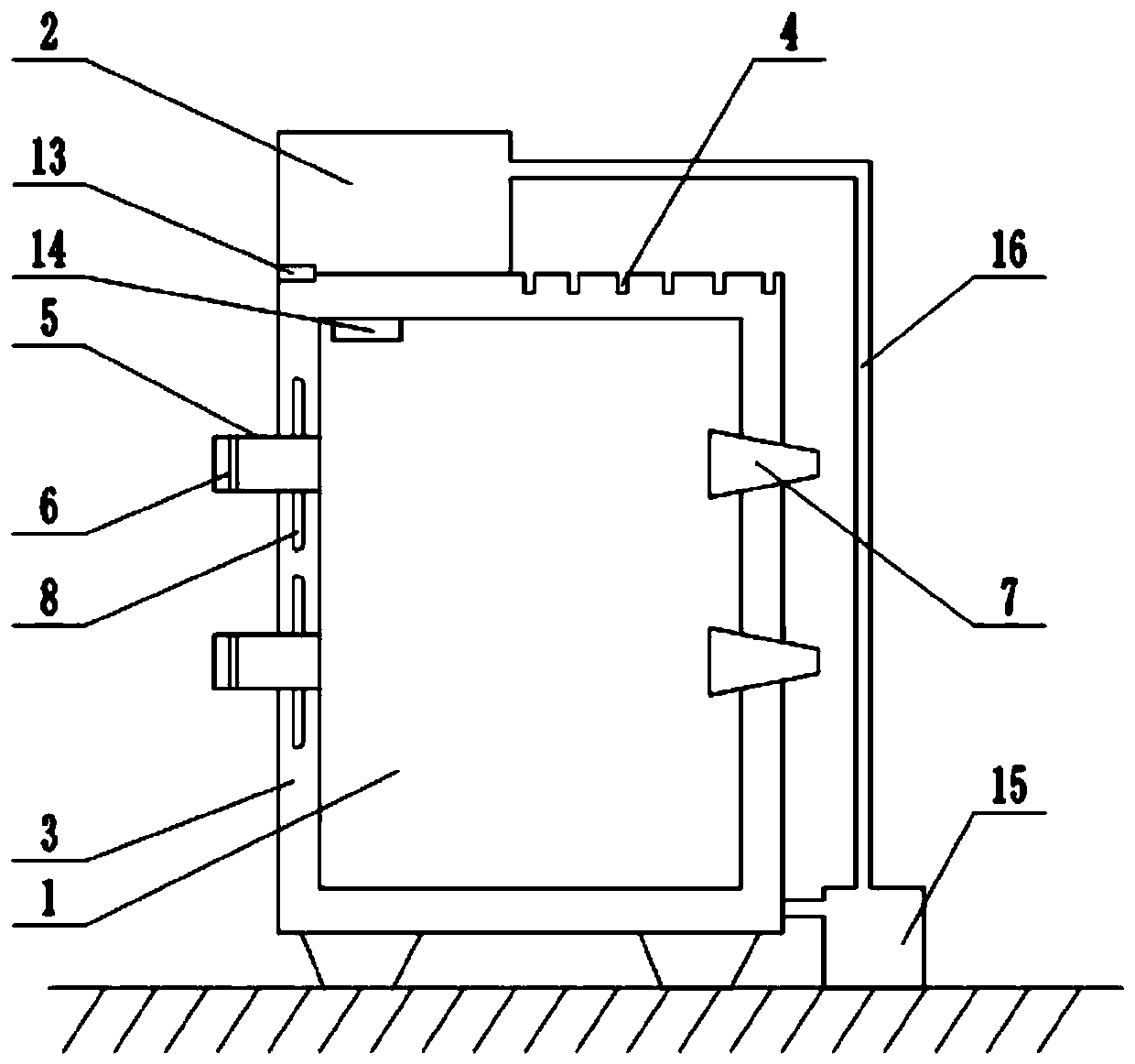
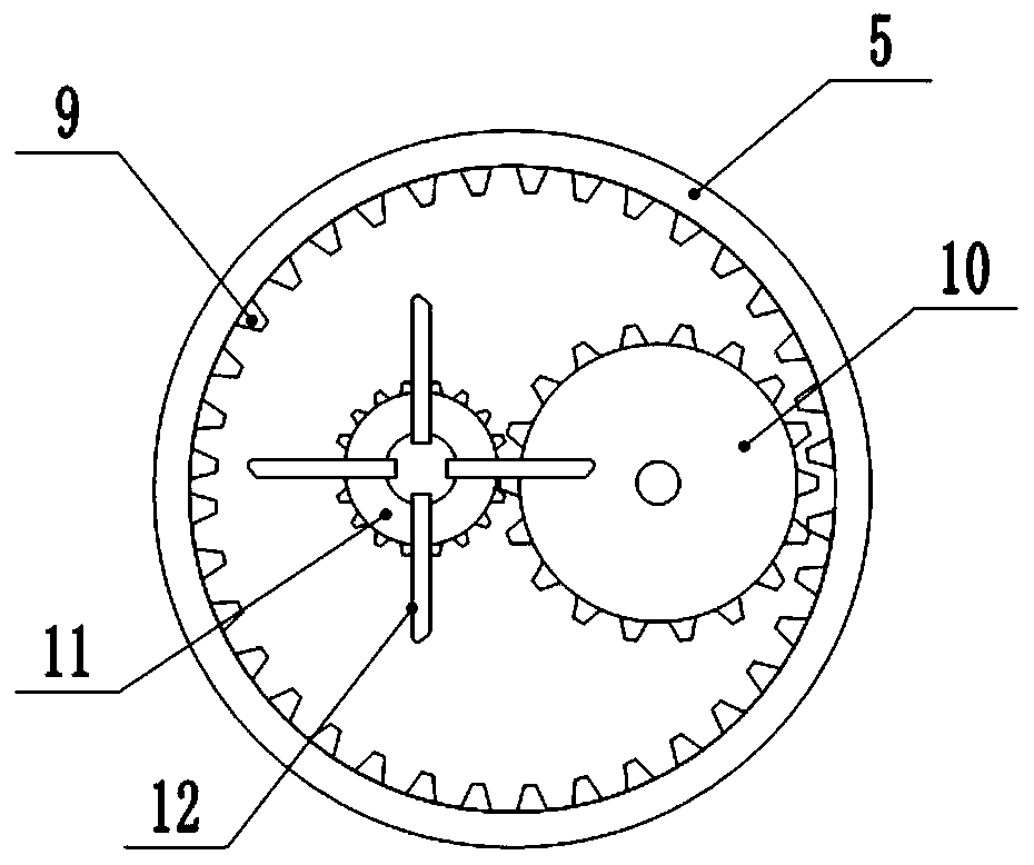
[0016] The reference signs in the drawings of the specification include: cabinet body 1, water tank 2, gap layer 3, vent hole 4, air inlet pipe 5, dustproof net 6, conical pipe 7, rotating blade 8, ring gear 9, first Gear 10, second gear 11, fan 12, control valve 13, temperature sensor 14, water pump 15, water pipe 16.

[0017] This embodiment is basically as figure 1 As shown, the adaptive control cabinet includes a cabinet body 1 and a water tank 2 fixedly connected to the cabinet body 1. The cabinet body 1 includes an inner wall and an outer wall, and a gap layer 3 is formed between the inner wall and the outer wall. The top of the outer wall of the cabinet body 1 is provided with a number of ventilation holes 4, and the side wall of the cabinet body 1 is rotatably connected with two air inlet pipes 5, the air inlet pipes 5 are set through the inner wall and the outer wall, and the inner bolt...


PUM


Abstract

The invention relates to the field of control cabinets, and specifically discloses an adaptive control cabinet. A cabinet body comprises an inner wall and an outer wall. A gap layer is formed betweenthe inner wall and the outer wall. Air inlet pipes are rotatably connected onto the cabinet body. The air inlet pipes penetrate through the inner wall and the outer wall. The cabinet body is providedwith air outlet pipes thereon disposed opposite to the air inlet pipes. A plurality of rotating blades are fixedly connected on the outer peripheral walls of the air inlet pipes along the circumference. The rotating blades are located in the gap layer. A gear ring is arranged on the inner wall of each air inlet pipe. Each gear ring meshes with a first gear. Each first gear meshes with a second gear. Each second gear is coaxially connected with a fan. The fans are rotatably connected onto the cabinet body. A water tank is connected with the gap layer with a pipeline. A control valve is providedon the pipeline. A temperature sensor is installed in the cabinet body. The temperature sensor is electrically connected with a controller. The controller is electrically connected with the control valve. The control cabinet in the invention has adaptability so that the control cabinet determines to control the heat dissipation by itself and the energy is saved.

Description

technical field [0001] The invention relates to the field of control cabinets, and specifically discloses an adaptive control cabinet. Background technique [0002] With the rapid development of science and technology, more and more high-tech products have entered people's lives, and more and more electronic components need to be installed in the communication cabinet. Require. The heat dissipation method adopted by the existing communication cabinets is usually: opening ventilation holes on the cabinet body and installing a fan in the cabinet body for ventilation and heat dissipation, but installing a fan in the cabinet body will occupy the internal capacity of the cabinet body, resulting in Electronic components are distributed more closely, increasing the thermal influence between electronic components. In addition, the fans in ordinary communication cabinets generally need to be manually controlled, or they have to be rotated to dissipate heat during the working hours ...

Claims


Application Information

Patent Timeline
Patent Type & Authority Patents(China)
IPC IPC(8): H05K7/20
CPCH05K7/20209
Inventor 张科
Owner 滁州伏特威电气技术有限公司
Learn More