A device for adjusting lighting

A technology of adjusting device and lighting lamp, which is applied in the field of lighting, can solve the problems of unable to adjust the angle of lighting light, unable to adjust the light intensity of lighting lamp, etc., and achieve the effect of reasonable structure design and simple operation.

Active Publication Date: 2019-11-12
YANGZHOU BENSE LIGHTING TECH CO LTD
View PDF3 Cites 0 Cited by
  • Summary
  • Abstract
  • Description
  • Claims
  • Application Information

AI Technical Summary

Problems solved by technology

[0003] The purpose of the present invention is to solve the problem that the existing illuminating lamps cannot adjust the light intensity and the angle of the illuminating light, and propose an adjusting device for the illuminating light, which can not only adjust the light intensity, but also adjust the angle of the illuminating light

Method used


Image

  • A device for adjusting lighting
  • A device for adjusting lighting
  • A device for adjusting lighting

Examples


Embodiment 1

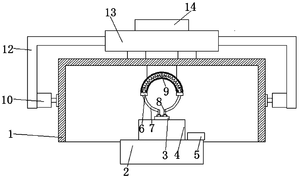
[0019] Embodiment 1: refer to Figure 1-2 , an adjusting device for an illuminating lamp, comprising a housing 1, a device chamber is provided inside the housing 1, a communication opening communicating with the device chamber is provided through the bottom side wall of the housing 1, and the inner top of the device chamber is fixedly connected There is a first suspension block, and the first suspension block is located between the two lifting devices, the bottom of the first suspension block is provided with a connecting device, the bottom of the connecting device is fixedly connected with a light adjuster 4, and the bottom side wall of the light adjuster 4 It is fixedly connected with the side wall of the upper end of the illuminating lamp 2, the upper end of the housing 1 is provided with a rotating device, and the upper end of the rotating device is provided with a connecting block 14, and the rotating device includes rotating shafts at both ends connected to the upper end ...

Embodiment 2

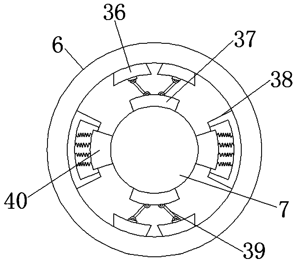
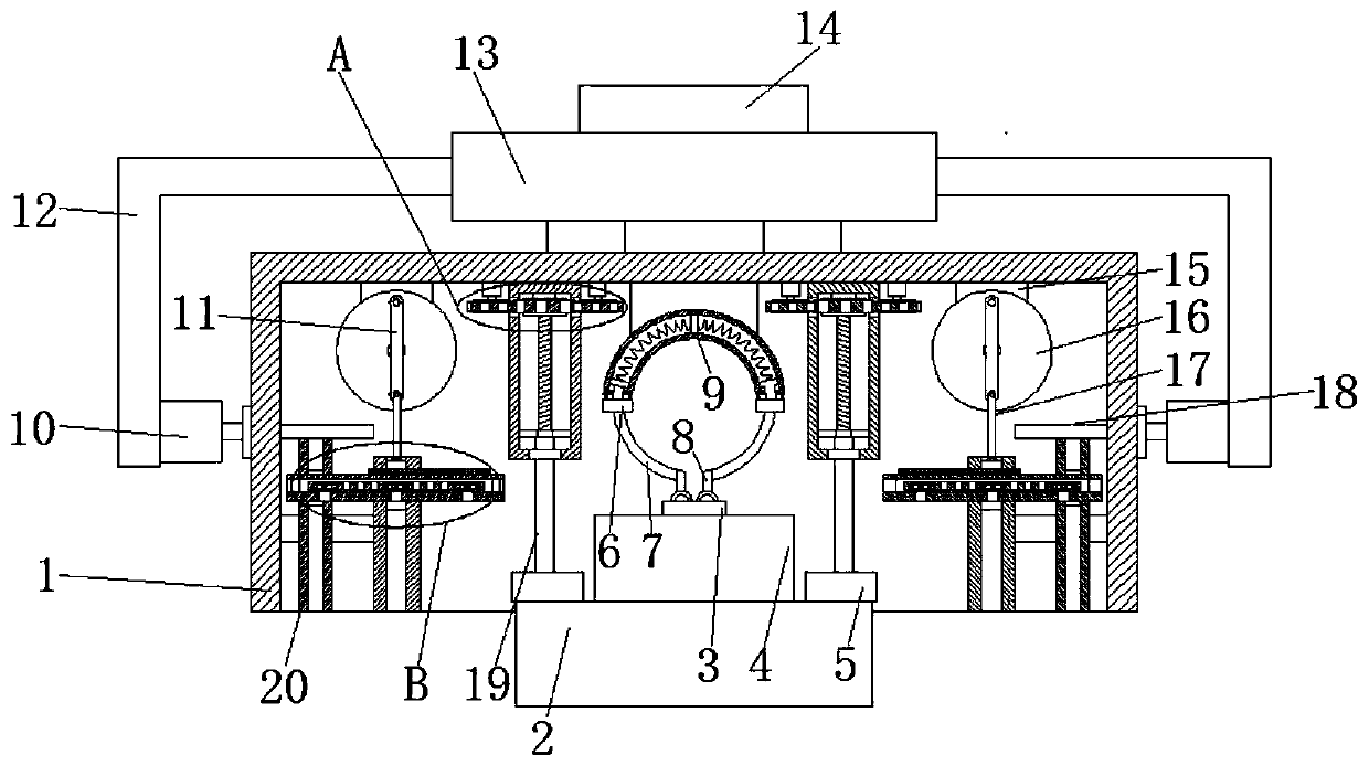
[0021] Embodiment 2: refer to Figure 2-6 , applying the present invention to a dimming device, including a housing 1, a device chamber is provided inside the housing 1, a communication opening communicating with the device chamber is provided through the bottom side wall of the housing 1, and the interior of the device chamber The top is symmetrically provided with two lifting devices, the lower ends of the two lifting devices are provided with fixed blocks 5, the bottoms of the two fixed blocks 5 are fixedly connected by the lighting lamp 2, and the inner top of the device cavity is fixedly connected with the first suspension block, and The first suspension block is located between the two lifting devices, the bottom of the first suspension block is provided with a connection device, the bottom of the connection device is fixedly connected with a light adjuster 4, and the bottom side wall of the light adjuster 4 is connected to the upper end side of the lighting lamp 2 The w...


PUM


Abstract

The invention discloses an adjusting device of an illuminating lamp. The adjusting device comprises a shell, a device cavity is formed in the shell, a communicating opening communicating with the device cavity is formed in the side wall of the bottom of the shell in a penetrating mode, a first suspension block is fixedly connected with the inner top of the device cavity, and a connecting device isarranged at the bottom of the first suspension block; a light ray adjuster is fixedly connected with the bottom of the connecting device, the side wall of the bottom of the light ray adjuster is fixedly connected with the side wall of the upper end of the illuminating lamp, a rotating device is arranged at the upper end of the shell, and a connecting block is arranged at the upper end of the rotating device; and the rotating device comprises two rotary shafts rotatably connected to the upper end of the shell, the upper ends of the two rotary shafts are rotatably connected through a rotating plate, and L-shaped plates are arranged at the two ends of the rotating plate correspondingly. According to the adjusting device, the structural design is reasonable, operation is easy, the light ray intensity can be adjusted, and the illuminating light ray angle can be adjusted as well.

Description

technical field [0001] The invention relates to the technical field of lighting, in particular to an adjusting device for a lighting lamp. Background technique [0002] With the continuous development of economic level and technological level, some products are becoming more and more specialized. As far as lighting lamps are concerned, traditional lighting lamps are simply for lighting. Since they are fixed on walls or rods, they cannot Angle adjustment and light adjustment, and with different usage conditions, users need a lighting that can be dimmed to solve the actual situation, so we designed a lighting adjustment device to solve the above problems. Contents of the invention [0003] The object of the present invention is to solve the problem that the existing illuminating lamps cannot adjust the light intensity and the angle of the illuminating light, and propose an adjusting device for the illuminating light, which can not only adjust the light intensity, but also ad...

Claims


Application Information

Patent Timeline
Patent Type & Authority Patents(China)
IPC IPC(8): F21V14/00B08B1/00
CPCB08B1/002F21V14/00
Inventor 薛贺龙
Owner YANGZHOU BENSE LIGHTING TECH CO LTD
Why Eureka
Try Eureka