Clip nail pusher structure for clip applier

A clip applier and nail clipping technology, applied in the field of medical equipment, can solve problems such as poor accuracy of the nail body, complex structure, and inability to clip the nails.

Active Publication Date: 2018-05-25
迈斯科生医股份有限公司
View PDF12 Cites 4 Cited by
  • Summary
  • Abstract
  • Description
  • Claims
  • Application Information

AI Technical Summary

Problems solved by technology

[0002] The known clip applier's nail pushing structure is a structure from the beginning to the end, so when the nail body is easily squeezed by force, it will The pitch is reduced, and it is two different driving elements, so the structure is more complicated, and the accura

Method used


Image

  • Clip nail pusher structure for clip applier
  • Clip nail pusher structure for clip applier
  • Clip nail pusher structure for clip applier

Examples


Embodiment Construction

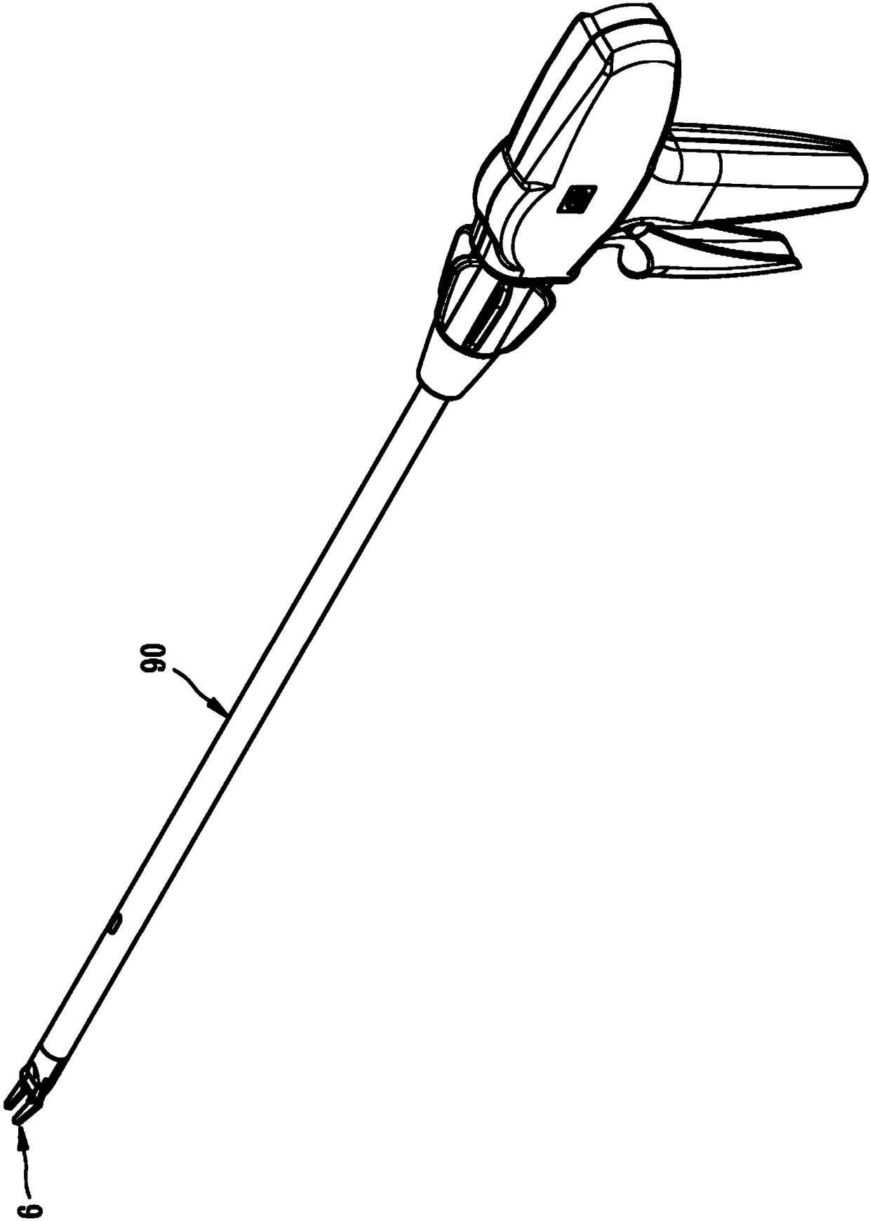
[0043] Below, now in conjunction with accompanying drawing and embodiment the present invention will be further described:

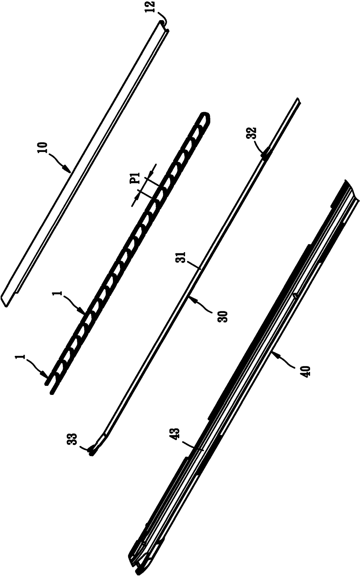
[0044] like Figure 1-Figure 8 As shown, the nail pushing structure of the clip applier provided by the present invention is used to install and push the nails 1 , wherein a nail distance P1 is formed between two nails 1 .

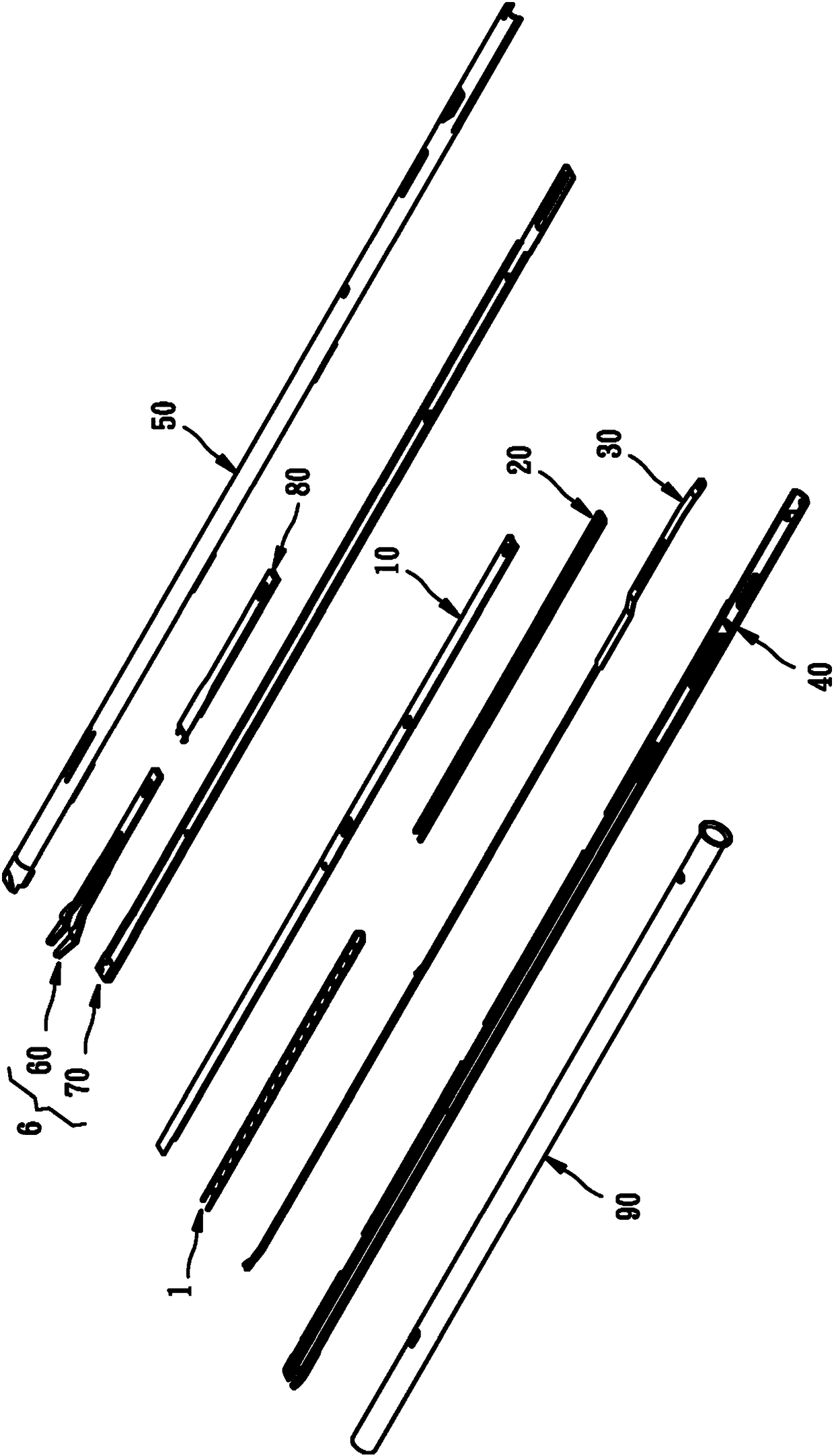
[0045] The nail pushing structure of the clip applier includes:

[0046] A nail groove part 10 has an accommodating groove 12 , a one-way anti-retraction part 13 arranged in the middle section, and a blocking piece 14 .

[0047] Wherein, the nail setting slot 10 has a one-way anti-retraction part 13 that unidirectionally blocks the pushed part 23 of the nail-feeding ladder 20, so as to control the nail-feeding ladder 20 to move forward but not backward.

[0048] Wherein, the clamping nail 1 is arranged in the accommodating groove 12 of the nail slot member 10 continuously and close to the ground.

[0049] A nail feeding ladder 20 ...


PUM


Abstract

A clip nail pusher structure for a clip applier is configured to install and push a clip nail, wherein a nail pitch is formed between every two clip nails; the clip nail pusher structure of the clip applier includes a nail mounting groove piece having a receiving slot, wherein the clip nails are continuously placed in the receiving slot of the nail mounting groove piece; and a screw-in ladder member having a nail-pushing part and a plurality of pushed parts with a distance between the every two pushed parts; a pusher member having a body; a front pusher portion that can push the foremost clipnail, and a rear pusher portion that can push each pushed part of the screw-in ladder member.

Description

technical field [0001] The invention relates to medical equipment, in particular to a clip nail pushing structure of a clip applier. Background technique [0002] The known clip applier's nail pushing structure is a structure from head to tail, so when the nail body is easily squeezed by force and its pitch is reduced, it is two different driving elements, so the structure It is relatively complicated, and the accuracy of pushing the nail body forward is poor, and it is easy to cause the frontmost nail body to not be in the correct position and the nail cannot be clamped. [0003] Therefore, the absence of the clip nail pushing structure of the prior art clip applier still needs to be improved. Contents of the invention [0004] In view of the above-mentioned defects in the prior art, the main purpose of the present invention is to provide a clip applier nail pushing structure, which is simple in structure and easy to operate, and can push the nail body forward more accur...

Claims


Application Information

Patent Timeline
IPC IPC(8): A61B17/128
CPCA61B17/1285A61B17/10A61B17/00234
Inventor 范宏扬黄士豪
Owner 迈斯科生医股份有限公司
Why Eureka
Try Eureka