
Symmetrical-stripe-and-check cutting method and system

A grid-aligning and strip-aligning technology, applied in the field of cutting bed, can solve the problems of low cutting efficiency and poor precision, and achieve the effect of reducing labor costs, reducing production costs, and saving time

Active Publication Date: 2018-05-18
BULLMER ELECTROMECHANICAL TECH
View PDF8 Cites 10 Cited by
  • Summary
  • Abstract
  • Description
  • Claims
  • Application Information

AI Technical Summary

Problems solved by technology

[0005] The technical problem to be solved by the present invention is to provide a strip-to-grid cutting method and system to solve the problems of low cutting efficiency and poor precision in the production of existing striped garments

Method used


Image

  • Symmetrical-stripe-and-check cutting method and system
  • Symmetrical-stripe-and-check cutting method and system

Examples


Embodiment 1

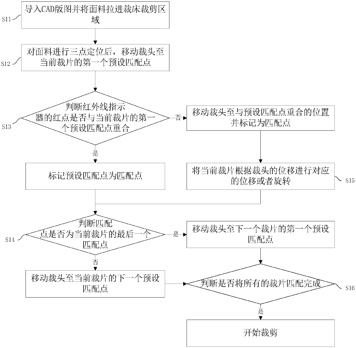
[0041] This embodiment provides a method for cutting the bars to the grid, such as figure 1 shown, including steps:

[0042] S11: Import the CAD layout and pull the fabric into the cutting area of ​​the cutting bed;

[0043] S12: After three-point positioning of the fabric, move the cutting head to the first preset matching point of the current piece;

[0044] S13: Determine whether the red point of the infrared indicator of the cutting head coincides with the first preset matching point of the current piece, if so, mark the preset matching point as the matching point; otherwise, move the cutting head to coincide with the preset matching point and marked as matching points;

[0045] S14: After marking the preset matching point as the matching point, judge whether the matching point is the last matching point of the current piece, if so, move the cutting head to the first preset matching point of the next piece; otherwise, move the cutting head To the next preset matching po...

Embodiment 2

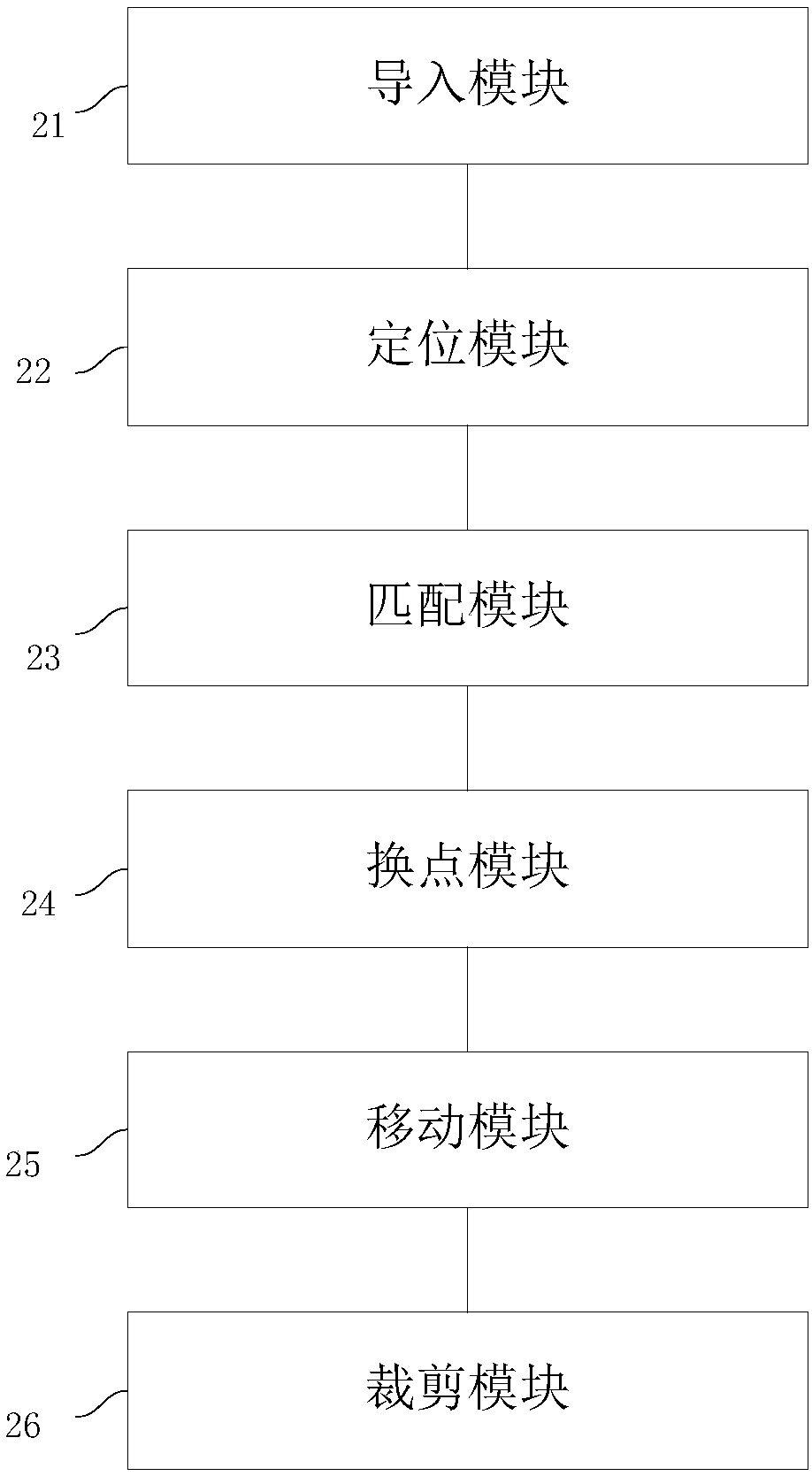
[0075] The present embodiment provides a kind of bar to grid cutting system, such as figure 2 shown, including:

[0076] The import module 21 is used to import the CAD layout and pull the fabric into the cutting bed cutting area;

[0077] The positioning module 22 is used to move the cutting head to the first preset matching point of the current piece after performing three-point positioning on the fabric;

[0078] Matching module 23 is used to judge whether the red point of the infrared indicator of the cutting head coincides with the first preset matching point of the current cut piece, if so, mark the preset matching point as the matching point; otherwise, move the cutting head to match the preset matching point. Set the position where the matching points coincide and mark it as a matching point;

[0079] Change the point module 24, after being used to mark the preset matching point as the matching point, judge whether the matching point is the last matching point of the...


PUM


Abstract

The invention discloses a symmetrical-stripe-and-check cutting method and system. The method and system are used for solving the problems that in existing stripe-check clothing production, the cuttingefficiency is low and the precision is poor. The method comprises the steps of importing a CAD map and drawling fabric into a cutting bed cutting area; moving a cutting head to a first preset matching point of a current cutting part after conducting three-point locating on the fabric; judging whether a red point of an infrared indicator of the cutting head coincides with the first preset matchingpoint of the current cutting part or not, and if yes, labeling the preset matching point as a matching point; if not, moving the cutting head to the position coinciding with the preset matching pointand labeling the position as the matching point. By means of the symmetrical-stripe-and-check cutting method and system, before cutting, the position of the cutting part in a cutting bed computer isadjusted through a matching stripe and check point method, the operation is simple and the time is saved. Besides, after cutting is conducted, manual cutting is not needed anymore, the production process steps are reduced, the efficiency is improved, and the production cost is reduced.

Description

technical field [0001] The invention relates to the technical field of cutting beds, in particular to a strip-to-grid cutting method and system. Background technique [0002] In the process of producing striped shirts in garment factories, because the stripes and grids of some shirt pieces need to be aligned, generally the pieces cut from some pieces will be larger, and manual work will require a grid. The cut pieces are matched and then manually trimmed. [0003] The current artificial electric scissors cutting, first use the marker paper on the striped fabric to match the required matching points, then use the needle to fix the marker paper and the fabric to prevent the marker paper from shifting, and then trim it, which is inefficient , poor precision. The current machine cutting uses the dry running method of the cutting head to observe the red dot of the infrared indicator. Whether the contour line of the red dot coincides with the contour line of the marker paper is ...

Claims


Application Information

Patent Timeline
Patent Type & Authority Applications(China)
IPC IPC(8): D06H7/00
CPCD06H7/00
Inventor 林世杰
Owner BULLMER ELECTROMECHANICAL TECH
Learn More