
Blinking robot eyeball

A robot and eyeball technology, applied in the field of bionics, which can solve the problems such as the inability of the eyeball to rotate and the imitation of eyeball rotation.

Active Publication Date: 2018-05-15
威海高新园区运营管理有限公司
View PDF7 Cites 1 Cited by
  • Summary
  • Abstract
  • Description
  • Claims
  • Application Information

AI Technical Summary

Problems solved by technology

The eyeballs in this device cannot move and cannot mimic eye movement

Method used


Image

  • Blinking robot eyeball
  • Blinking robot eyeball
  • Blinking robot eyeball

Examples


specific Embodiment approach 1

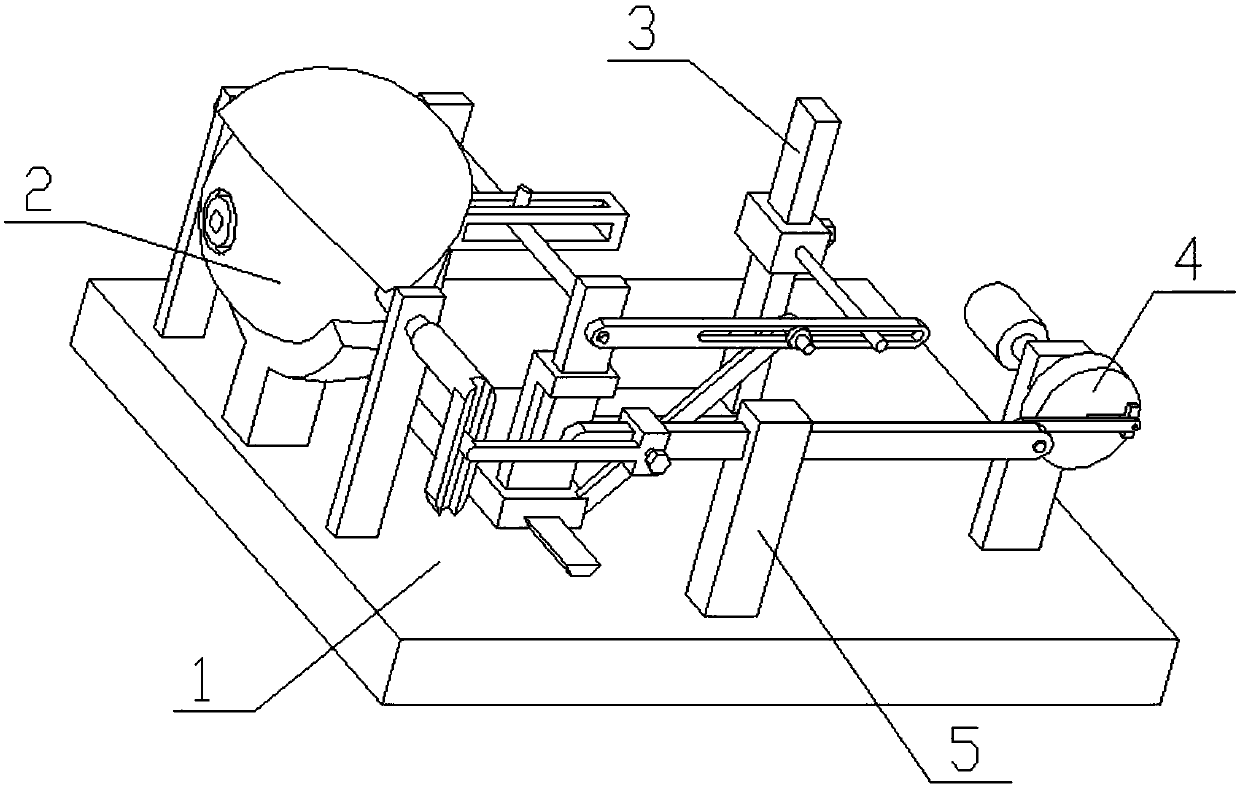
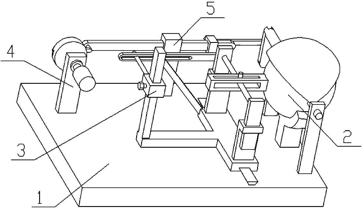
[0027] Combine below Figure 1-10 To explain this embodiment, the present invention relates to the field of bionics, more specifically, a blinkable robot eyeball, and more specifically a blinkable robot eyeball, including a base plate 1, an eyeball 2, an eyeball control component 3, and a blinking eye The frequency adjustment component 4 and the eyelid mechanism 5, the eyelid in the device can be rotated to imitate the blinking action, and the amplitude of the blink can be adjusted; and the eyeball in the device can be rotated in the horizontal and vertical directions, which more realistically imitates the movement of the eyeball.

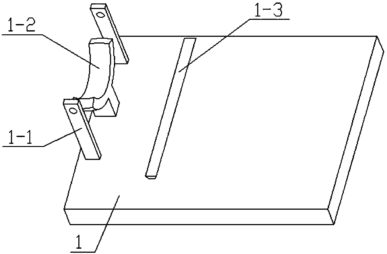
[0028] The bottom plate 1 is provided with a rotating frame rod 1-1, an eyeball bracket 1-2, and a trapezoidal convex strip 1-3. The left end of the bottom plate 1 is symmetrically fixedly connected with two rotating frame rods 1-1, two rotating frames The bottom plate 1 between the rods 1-1 is fixedly connected to the eyeball bracket 1-2, the eyeball...


PUM


Abstract

The invention relates to the field of bionics, in particular to a blinking robot eyeball. The blinking robot eyeball comprises a bottom plate, an eyeball body, an eyeball control assembly, a blink frequency regulation module and an eyelid mechanism; an eyelid part in the device can rotate and simulate a blink action, and the blinking amplitude can be adjusted; furthermore, the eyeball body in thedevice can rotate along the transverse direction and the vertical direction, so that the movement of the eyeball is more realistically simulated. The bottom plate is provided with rotating frame poles, an eyeball support frame and a trapezoid convex strip; the two rotating frame poles are symmetrically and fixedly connected with the left end of the bottom plate; the eyeball support frame is fixedly connected with the bottom plate between the two rotating frame poles; the eyeball body is placed at the upper end of the eyeball support frame; the eyeball body is in a spherical shape; the upper end of the eyeball support frame is jointed with the spherical surface of the eyeball body; the trapezoid convex strip is fixedly connected with the middle position of the upper end of the bottom plate;the blink frequency regulation module is arranged at the right end of the bottom plate.

Description

Technical field [0001] The invention relates to the field of bionics, and more specifically to a blinkable robot eyeball. Background technique [0002] A medical simulated human eye with application number CN201210163320.X. The present invention discloses a medical simulated human eye, in which: the drive motor of the blink transmission mechanism and the pupil change mechanism and the support plate are fixed on the base. The blinking drive motor is transmitted to the eyelid through the crank and rocker transmission mechanism to achieve blinking. The pupil drive motor drives the pupil change mechanism installed inside the eyeball to realize pupil change, the pupil size position judgment mechanism is connected to the pupil change mechanism, and the pupil change mechanism is also connected to the pupil photosensitive mechanism. The eyeball is connected to the base through the bracket plate. The present invention integrates the blinking function and the pupil change function in a w...

Claims


Application Information

Patent Timeline
Patent Type & Authority Applications(China)
IPC IPC(8): G09B23/28G09B9/00
CPCG09B9/00G09B23/28
Inventor 田宗佳
Owner 威海高新园区运营管理有限公司
Learn More