
Variable-frequency control constant-pressure air compression system for printing and dyeing textile equipment

A textile printing and dyeing, frequency conversion control technology, applied in the field of textile printing and dyeing, can solve the problems of high energy consumption, high operating power of the air compressor, and power loss in the air compression system of constant air pressure control, so as to achieve less power loss, avoid impact, and improve energy efficiency. The effect of low consumption

Inactive Publication Date: 2018-05-11
林建盛
View PDF0 Cites 1 Cited by
  • Summary
  • Abstract
  • Description
  • Claims
  • Application Information

AI Technical Summary

Problems solved by technology

[0002] At present, the conventional air compression system used in textile printing and dyeing equipment such as setting machines, cloth rolling machines, etc., includes air compressors, air storage tanks, pressure reducing valves, air filters and other parts, which are generally operated by two parallel air compressors. It is connected with the air storage tank to keep the air pressure constant. During this process, the motor of the air compressor is always running at full speed. The control of constant air pressure is generally achieved by loading or unloading the air compressor, and the operation of the air compressor The power is large, which leads to high energy consumption and serious power loss in the constant air pressure control of the air compression system

Method used


Image

  • Variable-frequency control constant-pressure air compression system for printing and dyeing textile equipment

Examples


Embodiment Construction

[0012] In the following, the present invention will be further described in conjunction with the accompanying drawings and specific embodiments, so as to understand more clearly the technical idea claimed in the present invention.

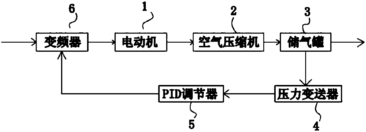
[0013] Such as figure 1 The shown air compression system for textile printing and dyeing equipment of the present invention is controlled by frequency conversion and constant pressure, including a motor 1, an air compressor 2, an air storage tank 3, a pressure transmitter 4, a PID regulator 5 and a frequency converter 6, and the motor 1 is a mouse Cage-type induction motor, the motor 1 is connected to the air compressor 2, the air compressor 2 is connected to the air storage tank 3, the exhaust end of the air storage tank 3 is connected to the gas device of the textile printing and dyeing equipment, and the pressure transmitter 4 is installed on On the gas storage tank 3, the frequency converter 6 is electrically connected to the motor 1 of the air...


PUM


Abstract

The invention discloses a variable-frequency control constant-pressure air compression system for printing and dyeing textile equipment. The variable-frequency control constant-pressure air compression system for the printing and dyeing textile equipment comprises a motor, an air compressor, an air storage tank, a pressure transmitter, a PID regulator and a frequency converter. The motor is in power connection with the air compressor. The air compressor is connected with the air storage tank. The pressure transmitter is mounted on the air storage tank. The frequency converter is connected withthe motor of the air compressor in an electric control mode. The pressure transmitter is connected with the frequency converter through the PID regulator. According to the variable-frequency controlconstant-pressure air compression system for the printing and dyeing textile equipment, the pressure transmitter is mounted on the air storage tank and connected with the frequency converter through the PID regulator, the frequency converter is connected with the motor of the air compressor in the electric control mode, and the rotating speed of the motor of the air compressor can be automaticallycontrolled through the frequency converter so as to achieve constant air pressure control; the variable-frequency control constant-pressure air compression system has the advantages of low energy consumption and low power loss; and in addition, the motor of the air compressor can be softly started to reach a stable rotating speed from the static state, and the influence of large current and mechanical impact generated when the motor is started to the air compressor is avoided.

Description

technical field [0001] The invention relates to the technical field of textile printing and dyeing, in particular to an air compression system for textile printing and dyeing equipment. Background technique [0002] At present, the conventional air compression system used in textile printing and dyeing equipment such as setting machines, cloth rolling machines, etc., includes air compressors, air storage tanks, pressure reducing valves, air filters and other parts, which are generally operated by two parallel air compressors It is connected with the air storage tank to keep the air pressure constant. During this process, the motor of the air compressor is always running at full speed. The control of constant air pressure is generally achieved by loading or unloading the air compressor, and the operation of the air compressor The power is large, which leads to high energy consumption and serious power loss in the air pressure constant control of the air compression system. ...

Claims


Application Information

Patent Timeline
Patent Type & Authority Applications(China)
IPC IPC(8): F04B35/04F04B41/02F04B49/06
CPCF04B35/04F04B41/02F04B49/06
Inventor 林建盛
Owner 林建盛
Learn More