Special equipment for dismounting pin shafts of hydraulic bracket

A hydraulic support and pin technology, applied in metal processing equipment, metal processing, manufacturing tools, etc., can solve the problems of shortened disassembly time, high labor intensity, and increased disassembly difficulty, so as to improve disassembly efficiency, avoid manual positioning, The effect of reduced disassembly time

Pending Publication Date: 2018-05-11
YANKUANG DONGHUA HEAVY IND CO LTD
View PDF0 Cites 4 Cited by
  • Summary
  • Abstract
  • Description
  • Claims
  • Application Information

AI Technical Summary

Problems solved by technology

However, with the increase of the tonnage and mining height of the hydraulic support, the specifications and models of the pin shafts connected between the various structural components also increase, and the difficulty of disassembly continues to increase. Therefore, it is particularly important to improve the way to disassemble the hydraulic support pin shaft necessary
[0003] Under normal circumstances, the hydraulic support has been operating in the mine for a long time, and the working environment is relatively harsh, resulting in severe corrosion and even serious deformation of the pin shaft of the hydraulic support, which further increases the difficulty of disassembling the pin shaft
[0004] At present, for the pin shafts of some small hydraulic supports, in the process of maintenance, the pin shafts of the hydraulic support are usually disassembled by traditional methods such as manual hammer hitting the pin shaft or gas cutting, which has a high work intensity and a long disassembly time. extremely inefficient
[0005] In addition, for the pin shafts of some large and medium-sized hydraulic supports, pulling tools such as hydraulic pin pullers are usually used to replace the traditional disassembly method. Manual loosening is required in advance, and most hydraulic pin pullers are inseparable from manual operation, the labor intensity is still high, the disassembly time has not been effectively shortened, and the disassembly efficiency is still low

Method used


Image

  • Special equipment for dismounting pin shafts of hydraulic bracket
  • Special equipment for dismounting pin shafts of hydraulic bracket

Examples


Embodiment Construction

[0065] The following will clearly and completely describe the technical solutions in the embodiments of the present invention with reference to the accompanying drawings in the embodiments of the present invention. Obviously, the described embodiments are only some, not all, embodiments of the present invention. Based on the embodiments of the present invention, all other embodiments obtained by persons of ordinary skill in the art without making creative efforts belong to the protection scope of the present invention.

[0066] In order to enable those skilled in the art to better understand the solution of the present invention, the present invention will be further described in detail below in conjunction with the accompanying drawings and specific embodiments.

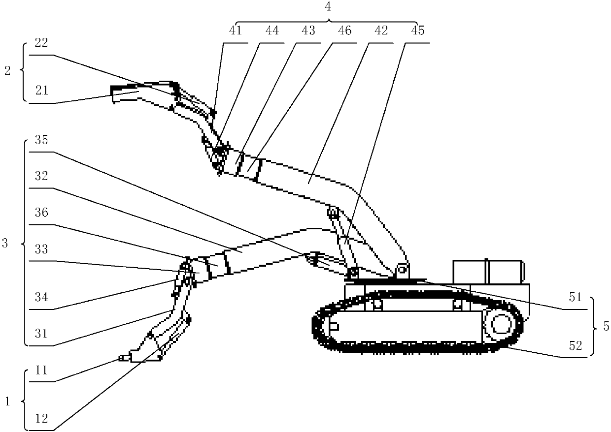
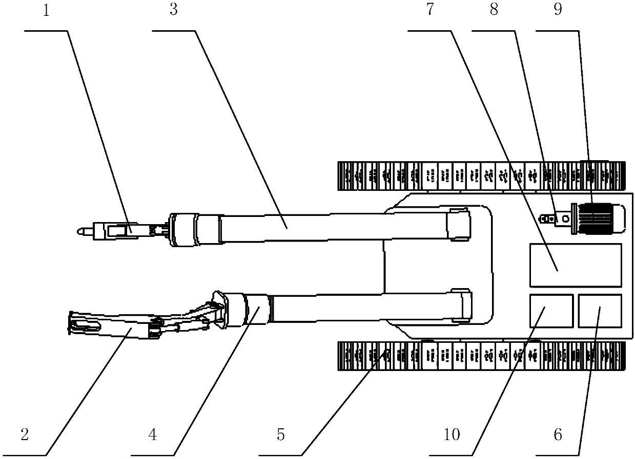
[0067] Please refer to figure 1 and figure 2 , figure 1 It is a schematic diagram of the front view of the special equipment for dismantling the pin shaft of the hydraulic support provided by a specific embodimen...


PUM


Abstract

The invention discloses special equipment for dismounting pin shafts of a hydraulic bracket. The special equipment comprises a vibration device, a pin withdrawing device, a vibration positioning device, a pin withdrawing positioning device and a walking rotation device, wherein the vibration device is used for loosening a pin shaft; the pin withdrawing device is used for withdrawing the pin shaft;the vibration positioning device is used for lifting or rotating the vibration device; the pin withdrawing positioning device is used for lifting or rotating the pin withdrawing device; and the walking rotation device is respectively connected with the vibration positioning device and the pin withdrawing positioning device and is used for driving the vibration positioning device and the pin withdrawing positioning device to walk. By utilizing the special equipment, the integrated and rapid vibration and dismounting can be realized through the vibration device and the pin withdrawing device, and pin shafts at different positions can be simultaneously loosened and dismounted, so that the integral working time is shortened, and the working efficiency is improved; and the automation can be realized, the manual operation for loosening or dismounting the pin shaft is omitted, the labor intensity is alleviated, and the dismounting efficiency is further improved. Therefore, the dismounting efficiency of the pin shafts of the pin shafts of the hydraulic bracket can be effectively improved.

Description

technical field [0001] The invention relates to the technical field of mining equipment, in particular to a special equipment for dismounting a pin shaft of a hydraulic support. Background technique [0002] As one of the important equipment for coal mining, hydraulic support usually includes top beam, cover beam, connecting rod and base. Generally, the hydraulic support is a four-bar linkage mechanism that realizes roof support by lifting and lowering. Naturally, various structural components can be connected as a whole through several pin shafts. However, with the increase of the tonnage and mining height of the hydraulic support, the specifications and models of the pin shafts connected between the various structural components also increase, and the difficulty of disassembly continues to increase. Therefore, it is particularly important to improve the way to disassemble the hydraulic support pin shaft necessary. [0003] Usually, the hydraulic support has been operated...

Claims


Application Information

Patent Timeline
Patent Type & Authority Applications(China)
IPC IPC(8): B23P19/00
CPCB23P19/00
Inventor 徐明阳孙强李同吴成峰刘宝新曾永陈凯王孝杰刘将
Owner YANKUANG DONGHUA HEAVY IND CO LTD
Why Eureka
Try Eureka