
Method for detecting liquid crystal module by using liquid crystal module automatic optical detection system

An automatic optical detection, liquid crystal module technology, applied in optics, nonlinear optics, instruments, etc., can solve the problems of unable to cover detection standards, poor detection system performance, low detection efficiency, etc., to improve detection efficiency and detection accuracy, The effect of reducing the impact and reducing the workload

Active Publication Date: 2020-07-10
航天科工智能机器人有限责任公司
View PDF7 Cites 0 Cited by
  • Summary
  • Abstract
  • Description
  • Claims
  • Application Information

AI Technical Summary

Problems solved by technology

The manual detection method is greatly affected by human subjective factors, the detection efficiency is low, and the damage to the human eye is large; the domestic liquid crystal module detection equipment detects Mura through vision, the false detection rate is high, and the performance of the detection system is poor , and cannot cover all the testing standards of module manufacturers

Method used


Image

  • Method for detecting liquid crystal module by using liquid crystal module automatic optical detection system
  • Method for detecting liquid crystal module by using liquid crystal module automatic optical detection system
  • Method for detecting liquid crystal module by using liquid crystal module automatic optical detection system

Examples


Embodiment Construction

[0042] The present disclosure will be further described in detail below in conjunction with the accompanying drawings and embodiments. It should be understood that the specific embodiments described here are only used to explain relevant content, rather than to limit the present disclosure. It should also be noted that, for ease of description, only parts related to the present disclosure are shown in the drawings.

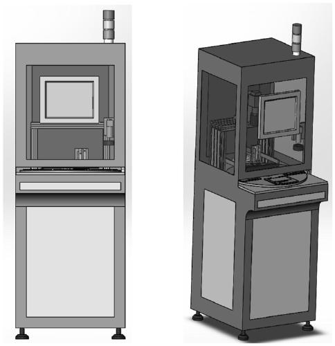
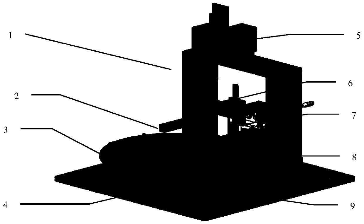
[0043] It should be noted that, in the case of no conflict, the embodiments in the present disclosure and the features in the embodiments can be combined with each other. The following will refer to the attached Figure 1-6 The present disclosure will be described in detail in combination with embodiments.

[0044] Liquid crystal module automatic optical inspection system, including visual inspection system, automatic electrical docking system and industrial computer;

[0045] The visual inspection system is used to collect images of liquid crystal modules to b...


PUM


Abstract

Disclosed is an automatic optical detection system of a liquid crystal module. The system includes a vision detection system, an electrical docking system and an industrial personal computer; the vision detection system is used for collecting images of the liquid crystal module to be detected; the industrial personal computer is used for analyzing the images collected by the vision detection system; the electrical docking system is used for achieving electrical ducking of the liquid crystal module to be detected and the vision detection system.

Description

technical field [0001] The disclosure relates to the technical field of industrial automation, in particular to a method for detecting a liquid crystal module by using an automatic optical detection system for a liquid crystal module. Background technique [0002] At present, the overall level of intelligent automation in the domestic 3C industry is low. According to the research and analysis of the domestic mobile phone screen industry, most manufacturers use two detection methods for mobile phone screens, namely manual detection and domestic LCD module detection equipment detection. The manual detection method is greatly affected by human subjective factors, the detection efficiency is low, and the damage to the human eye is large; the domestic liquid crystal module detection equipment detects Mura through vision, the false detection rate is high, and the performance of the detection system is poor , and cannot cover all the testing standards of module manufacturers. Con...

Claims


Application Information

Patent Timeline
Patent Type & Authority Patents(China)
IPC IPC(8): G02F1/13
CPCG02F1/1309
Inventor 郁肖飞张衡洪群生蒋振东刘遥峰郝鹏
Owner 航天科工智能机器人有限责任公司
Learn More