Media conveying device and image forming device

A medium conveying and medium technology, which is applied in the field of medium conveying devices and image forming devices, can solve problems such as damage to components and media, and achieve the effect of improving operability

Active Publication Date: 2021-08-06
COPYER
View PDF12 Cites 0 Cited by
  • Summary
  • Abstract
  • Description
  • Claims
  • Application Information

AI Technical Summary

Problems solved by technology

In addition, the reason why the operator needs to remove the medium from the rotating body (for example, it cannot be automatically discharged) is because: when the conveying length is shorter than the predetermined length, the end rotation trajectory of the medium held by the rotating body will be different from that arranged on the rotating body. Interference with surrounding components (sensors, etc.) may cause damage to the components and the medium itself

Method used


Image

  • Media conveying device and image forming device
  • Media conveying device and image forming device
  • Media conveying device and image forming device

Examples


Embodiment Construction

[0043] Hereinafter, an embodiment in which the present invention is applied to a printing device for printing and recording characters and images on a card and magnetically or electrically recording information on the card will be described.

[0044] 1. Structure

[0045] 1-1. System structure

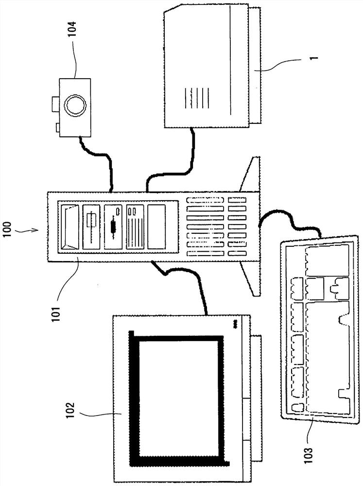
[0046] like figure 1 and Image 6 As shown, the printing apparatus 1 of this embodiment constitutes a part of the printing system 100 . That is, the printing system 100 is basically composed of a higher-level device 101 (for example, a host computer such as a personal computer) and a printing device 1 .

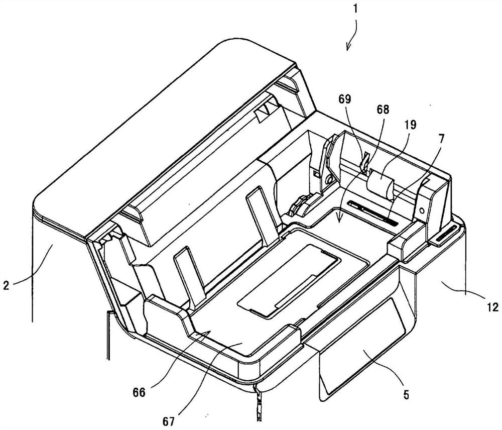
[0047] The printing device 1 is connected to a host device 101 via an interface not shown, and can transmit printing data, magnetic or electrical recording data, etc., and instruct a recording operation, etc., from the host device 101 to the printing device 1 . In addition, the printing apparatus 1 has an operation panel unit (operation display unit) 5 (see image 3 , Image 6 )...


PUM


Abstract

The present invention provides a medium conveying device capable of improving operability when clogging occurs. The printing device includes: a conveyance roller that conveys the card; a rotation unit that holds and rotates the card; sensors (SN2, SN26) that detect the conveyance length of the card being conveyed; and a control unit. When the card conveying length detected by the sensors (SN2, SN26) is different from the predetermined length L1 (affirmative judgment in S320), the control section judges whether the card can be positioned in the direction where the card can be taken out by the rotation unit ( S328, S336), when it is determined that it is possible, control the rotation motor that rotates the rotation unit to position the card in a direction where it can be taken out.

Description

technical field [0001] The present invention relates to a medium conveyance device and an image forming apparatus, and particularly to a medium conveyance device provided with a direction changing member for changing the conveyance direction of a medium, and an image forming apparatus provided with the medium conveyance device. Background technique [0002] Conventionally, image forming apparatuses for forming images on hard or semi-rigid media such as cards and magnetic disks are widely known. In such an image forming apparatus, for example, an indirect printing method of forming an image (mirror image) on a transfer film using a ribbon or a direct printing method, and then transferring the image formed on the transfer film to The surface of the medium, the direct printing method forms an image directly on the medium using a ribbon. [0003] In such an image forming apparatus, the image forming unit forms an image on the medium by heating the thermal head through the ink r...

Claims


Application Information

Patent Timeline
Patent Type & Authority Patents(China)
IPC IPC(8): B65H5/06G06K13/067B41J13/00B41J29/00
CPCB41J13/009B41J29/00B65H5/062G06K13/067B65H2404/15B65H2404/14B41J2/325B65H29/62B65H43/04B65H29/60B65H7/06B41J2/32G06K17/0016
Inventor 相原裕一
Owner COPYER
Why Eureka
Try Eureka