
Display device and its pixel array

A technology of pixel array and pixel column, which is applied in the direction of static indicators, instruments, semiconductor devices, etc., can solve problems such as jaggedness, and achieve the effect of alleviating jaggedness

Active Publication Date: 2020-05-19
EVERDISPLAY OPTRONICS (SHANGHAI) CO LTD
View PDF5 Cites 0 Cited by
  • Summary
  • Abstract
  • Description
  • Claims
  • Application Information

AI Technical Summary

Problems solved by technology

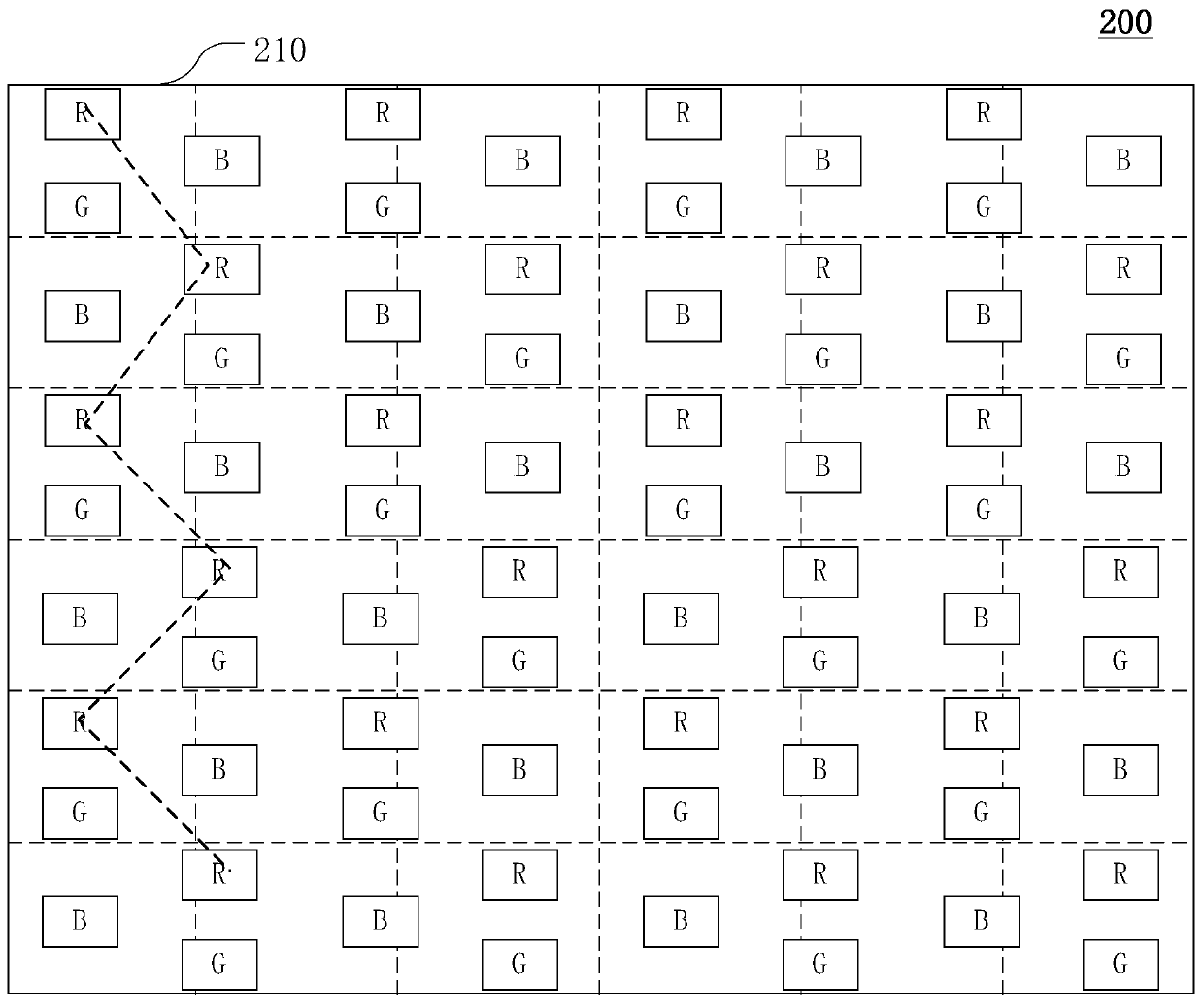
Such pixel array 200 can block figure 1 The faint black straight line in , but when it displays a monochrome straight line, it will produce a jagged problem (as shown by the dashed broken line)

Method used


Image

  • Display device and its pixel array
  • Display device and its pixel array
  • Display device and its pixel array

Examples


no. 1 example

[0035] see Figure 4 , Figure 4 A schematic diagram of a pixel array 400 according to the first embodiment of the present invention is shown. The pixel array 400 includes a first pixel column 411 and a second pixel column 412 arranged at intervals along the X direction (ie row direction). In other words, the first pixel column 411 and the second pixel column 412 are repeatedly arranged in the order of the first pixel column 411 and the second pixel column 412 along the X direction.

[0036] The first pixel column 411 includes a plurality of first pixels 421 arranged along the Y direction (ie column direction). The first pixel 421 includes a first sub-pixel P1 , a second sub-pixel P2 and a third sub-pixel P3 displaying different colors. The Y direction has the same Figure 4The direction of the first vector is the same as the direction of the arrow representing the Y direction, and the direction of the second vector is opposite to the direction of the first vector (that is...

no. 2 example

[0043] see Figure 5 , Figure 5 The pixel array 500 shown is similar to the pixel array 400, and the difference from the pixel array 400 is that in the X direction, the third sub-pixel P3 is aligned, and the first sub-pixel P1 and the second sub-pixel P2 are arranged according to the first sub-pixel P1, The second sub-pixel P2, the second sub-pixel P2, and the first sub-pixel P1 are arranged repeatedly as a unit. This embodiment can also alleviate the problem of displaying black straight lines and jagged solid-color images in the prior art on P3 solid-color images.

no. 3 example

[0045] see Figure 6 , Figure 6 The pixel array 600 shown is similar to the pixel array 400 , and the difference from the pixel array 400 is that in the same pixel column, the first sub-pixels P1 and the second sub-pixels P2 are arranged repeatedly at intervals along the Y direction. In this embodiment, the pixel array 600 can repair the phenomenon of display burrs by using the driving algorithm of the sub-pixels of adjacent pixels, and can also alleviate the display problem of black straight lines or jagged straight lines in the P3 solid color screen in the prior art.


PUM


Abstract

The present invention provides a pixel array and a display device. The pixel array includes a first pixel column and a second pixel column repeatedly arranged at intervals along the row direction, and the first pixel column includes a plurality of first pixels arranged along the column direction. In the pixel, the first sub-pixel, the second sub-pixel and the third sub-pixel are arranged in a triangle, one side of the triangle arrangement of the first pixel is parallel to the row direction, and the vertex opposite to the side is the third sub-pixel and is located at the The first vector direction of the side, the second pixel column includes a plurality of second pixels arranged along the column direction, in the second pixel, the first sub-pixel, the second sub-pixel and the third sub-pixel are arranged in a triangle, A side of the triangular arrangement of the second pixel is parallel to the row direction, the vertex opposite to the side is the third sub-pixel and is located in the second vector direction of the side, and the first pixel column and the second pixel column are in the column direction Stagger the first distance. The invention provides a display device and its pixel array, which improves the display effect of the display device.

Description

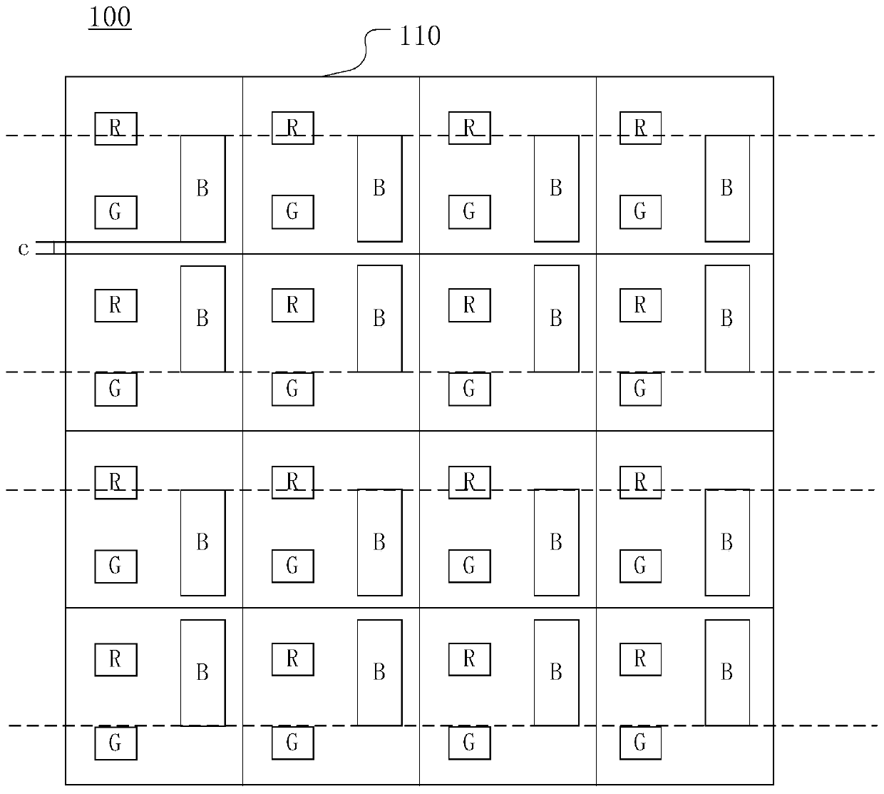
technical field [0001] The present invention relates to the field of display technology, in particular to a display device and a pixel array thereof. Background technique [0002] In recent years, OLED (Organic Light-Emitting Diode, Organic Light-Emitting Diode) technology has developed rapidly, and has become a promising technology most likely to replace LCD (Liquid Crystal Display, Liquid Crystal Display). [0003] A display panel in the prior art includes a substrate and a pixel array on the substrate. The pixel array includes a plurality of pixel units, and each pixel unit is composed of three sub-pixels of different colors. Each sub-pixel is connected to a scan line and a data line on the substrate, the scan line selects the sub-pixel, and the sub-pixel performs display according to the signal of the data line, thereby enabling the display panel to display images. [0004] In an example of prior art, such as figure 1 As shown, the pixel array 100 includes a plurality ...

Claims


Application Information

Patent Timeline
Patent Type & Authority Patents(China)
IPC IPC(8): H01L27/32
CPCG09G2300/0452H10K59/353
Inventor 高志豪陈凯凯屈晓娟王国兵
Owner EVERDISPLAY OPTRONICS (SHANGHAI) CO LTD
Learn More