ball screw

A technology of ball screw and lead screw, which is applied in the direction of transmission, belt/chain/gear, mechanical equipment, etc., and can solve the problem of unrealized load distribution and other problems

Active Publication Date: 2020-07-07
SCHAEFFLER TECH AG & CO KG
View PDF5 Cites 0 Cited by
  • Summary
  • Abstract
  • Description
  • Claims
  • Application Information

AI Technical Summary

Problems solved by technology

Since the ball groove on the nut side is interrupted by an elongated recess in this transmission concept, an optimal load distribution on the individual ball rows is not achieved

Method used


Image

  • ball screw
  • ball screw
  • ball screw

Examples


Embodiment Construction

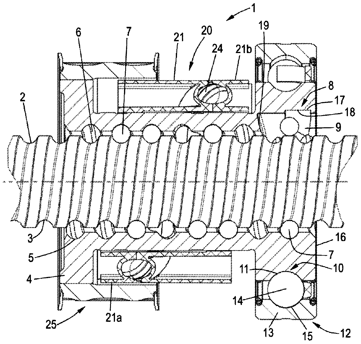
[0031] figure 1 Shows the ball screw 1 according to the present invention, the ball screw comprising: a screw 2 having a ball groove 3 formed on the outer side thereof; and a nut 4, the nut 4 being cut away here It is shown that the nut has a ball groove 5 formed on its inner side. The ball grooves 3 and 5 are supplemented in a known manner as a surrounding ball channel 6 in which the ball 7 travels.

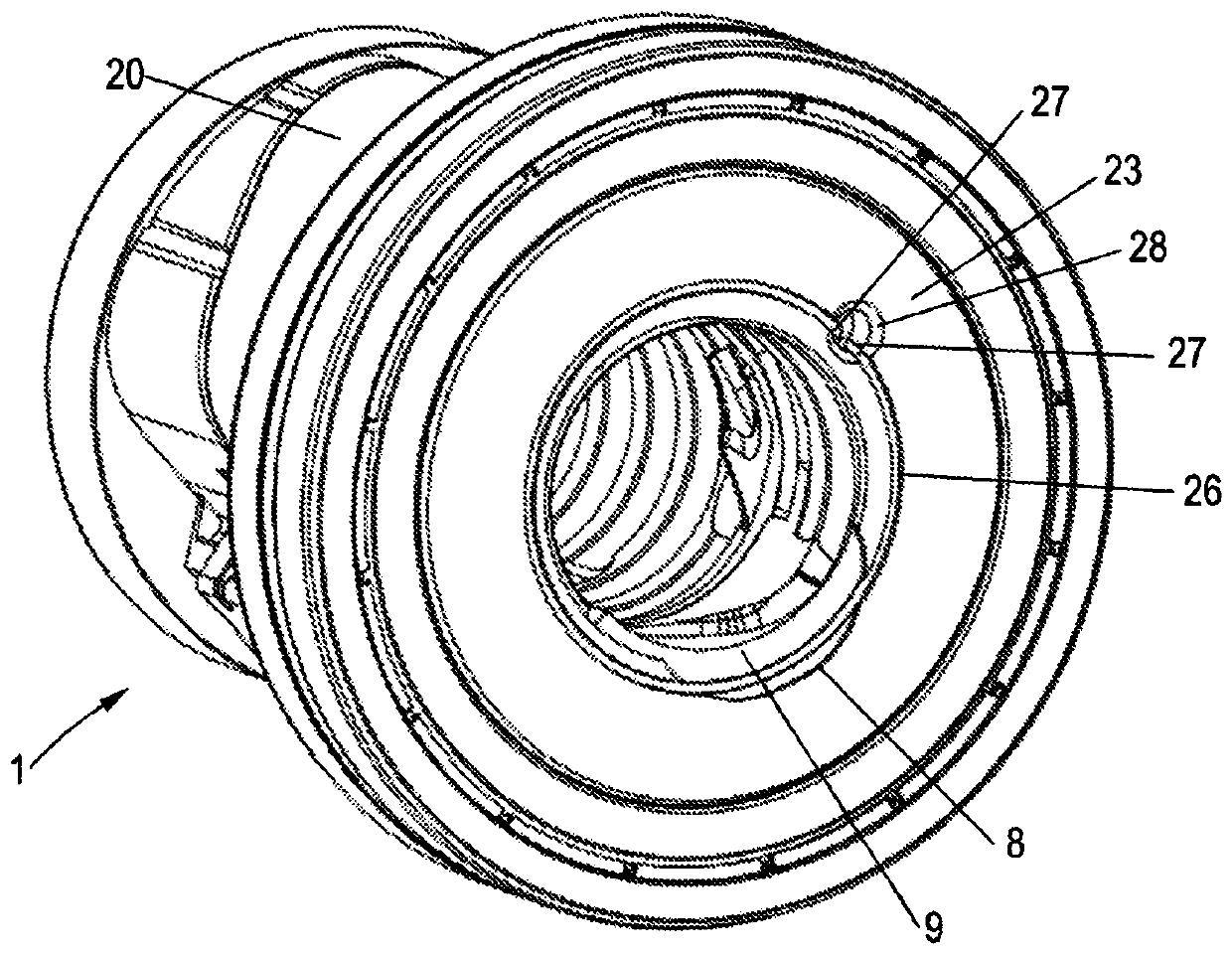
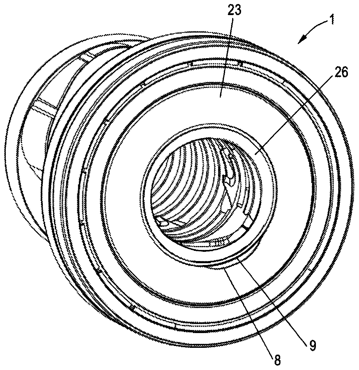
[0032] On the inner side of the nut 4, namely in the ball groove 5, a groove 8 is formed in which a steering element 9 is housed, and the steering element is used to steer the ball 7 from one channel section to the adjacent In the channel section, a surrounding closed ball row is formed. The steering element 9 is formed as a single steering element by means of which the ball 7 is displaced from one channel section via a threaded shoulder into the directly adjacent channel section.

[0033] The groove 8 is closed radially. This makes it possible to form an integrated bearing geomet...


PUM


Abstract

A ball screw comprising: a screw (2) having at least one outer ball groove (3); and a nut (4) having at least one inner ball groove (5), said ball grooves (3, 5) supplemented by ball channels (6), in which balls (7) are accommodated, via which balls guide the screw (2) relative to the nut (4), In this, in the ball groove (5) of the nut (2) at least one radially closed groove (8) is introduced, in which groove a deflecting element (9) is accommodated for turning in the ball groove (5) The traveling ball (7) is deflected, wherein the nut (4) has an outer deflection device (20) arranged on its outer side, said external deflection device being located axially in front of the deflection element (9) formed as a single deflection element , said outer diverter engages into two radial openings (22) in the nut (4) and via said outer diverter the balls (7) are axially staggered.

Description

Technical field [0001] The present invention relates to a ball screw. The ball screw includes: a screw with at least one outer ball groove; and a nut with at least one inner ball groove, which complements Ball channel, in which the ball is accommodated, the screw is guided relative to the nut via the ball, wherein at least one radially closed groove is introduced into the ball groove of the nut, and the steering is accommodated in the groove Element, used to turn the ball traveling in the ball groove. Background technique [0002] Ball screws are commonly used to convert rotational motion into movement (translation). For this, the screw or nut is connected to the drive, in particular the electric motor, if necessary, via an intermediate transmission mechanism. When the screw is rotated by the driver, the nut moves axially, that is, along the longitudinal direction of the screw, and the nut is connected to the screw via a ball arranged in the raceway. If the nut is instead coup...

Claims


Application Information

Patent Timeline
Patent Type & Authority Patents(China)
IPC IPC(8): F16H25/22
CPCF16H25/2219F16H2025/2096F16H25/2223F16H2025/2081
Inventor 马里奥·克罗伊策格尔德·萨内夫斯基纳丁·克利曼
Owner SCHAEFFLER TECH AG & CO KG
Why Eureka
Try Eureka