
a hemostatic device

The technology of a hemostatic cotton and a control device is applied in the field of medical devices, which can solve the problems of difficult operation, compression, complex structure, etc., and achieve the effects of low cost and convenient control.

Inactive Publication Date: 2020-09-01
毛水香
View PDF6 Cites 0 Cited by
  • Summary
  • Abstract
  • Description
  • Claims
  • Application Information

AI Technical Summary

Problems solved by technology

[0002] At present, most of the hemostatic methods used in medical treatment are manual compression to stop bleeding, using sterile cotton balls or hemostatic bandages. In the actual implementation process, too much pressure is applied manually, which may easily cause numbness and shaking of the affected part of the patient, or even ischemia, and it is more likely to compress the artery. Blood vessels affect the patient’s recovery. Too little manual pressure can easily cause bleeding and edema in the patient’s affected area. This method of hemostasis requires manual finger pressure or bandaging, which increases the workload of medical staff, wastes time, and is difficult to control. , most of the existing hemostatic devices are airbag pressurized hemostats, which need to inflate and pressurize the airbag to achieve compression and hemostasis on the affected area. The structure is generally complicated and difficult to operate

Method used


Image

  • a hemostatic device

Examples


Embodiment Construction

[0025] The present invention will be further described below in conjunction with accompanying drawing:

[0026] In order to make the purpose, technical solutions and advantages of the present invention clearer, the technical solutions in the present invention are clearly and completely described below. Apparently, the described embodiments are part of the embodiments of the present invention, not all of them. Based on the embodiments of the present invention, all other embodiments obtained by persons of ordinary skill in the art without creative efforts fall within the protection scope of the present invention.

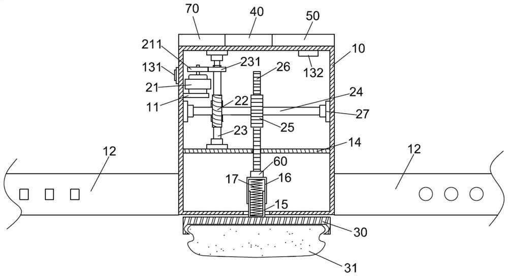
[0027] Refer to attached figure 1 , the present invention provides a hemostatic device, comprising a housing 10, a control device and a compression plate 30; the control device is disposed inside the housing 10, the compression plate 30 is disposed outside the housing 10, and the surface of the compression plate 30 is detachably connected with Hemostatic cotton 31. ...


PUM


Abstract

The invention discloses a hemostasis device. The hemostasis device comprises a shell, a control device and an oppressing plate; the control device is arranged in the shell, the oppressing plate is arranged outside the shell, and hemostasis cotton is detachably connected to the surface of the oppressing plate; the control device comprises a motor, a worm wheel, a worm, a driving shaft, a driving gear and a rack; a first supporting plate is fixedly connected to the inner wall of the shell, the motor is fixedly connected with the first supporting plate, a driving gear is fixedly connected to an output shaft of the motor, a driven gear is fixedly connected to the worm, and the driving gear is engaged with the driven gear; bearing bases are connected to the two ends of the driving shaft and fixedly connected with the inner wall of the shell, the worm wheel and the driving gear are fixedly connected with the driving shaft, the worm wheel is engaged with the worm, and the rack is engaged withthe gears, and drives the oppressing plate to move; the shell also comprises a switch assembly and pair of wrist bands. The hemostasis device is simple in structure, the hemostasis cotton can be replaced many times, a control assembly has the self-locking function, and meanwhile a pressure display and an alarm apparatus are arranged; the practicability is high.

Description

technical field [0001] The invention belongs to the technical field of medical instruments, and in particular relates to a hemostatic device. Background technique [0002] At present, most of the hemostatic methods used in medical treatment are manual compression to stop bleeding, using sterile cotton balls or hemostatic bandages. In the actual implementation process, too much pressure is applied manually, which may easily cause numbness and shaking of the affected part of the patient, or even ischemia, and it is more likely to compress the artery. Blood vessels affect the patient’s recovery. Too little manual pressure can easily cause bleeding and edema in the patient’s affected area. This method of hemostasis requires manual finger pressure or bandaging, which increases the workload of medical staff, wastes time, and is difficult to control. , most of the existing hemostatic devices are airbag pressurized hemostats, which need to inflate and pressurize the airbag to achiev...

Claims


Application Information

Patent Timeline
Patent Type & Authority Patents(China)
IPC IPC(8): A61B17/12
CPCA61B17/12A61B2017/12004
Inventor 毛水香黎怡郭联锋
Owner 毛水香
Learn More