
Electric leakage protection circuit and method and applicative driving device

A technology of leakage protection and driving device, applied in emergency protection circuit devices, circuit devices, emergency protection devices with automatic disconnection, etc.

Pending Publication Date: 2018-03-16
SHANGHAI BRIGHT POWER SEMICONDUCTOR CO LTD
View PDF0 Cites 16 Cited by
  • Summary
  • Abstract
  • Description
  • Claims
  • Application Information

AI Technical Summary

Problems solved by technology

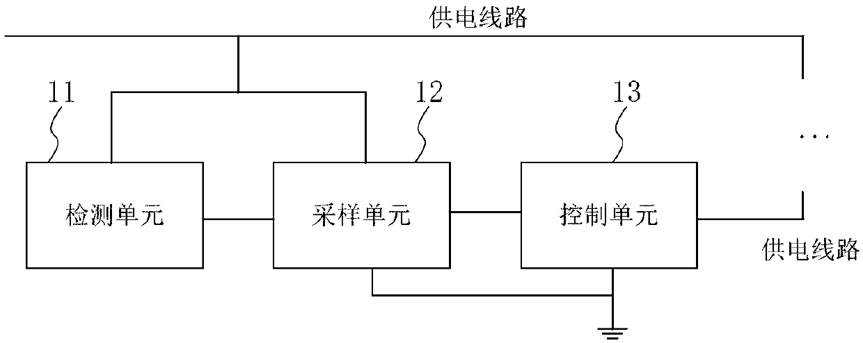
[0003] In view of the shortcomings of the prior art described above, the purpose of this application is to provide a leakage protection circuit, method and applicable driving device, which are used to solve the problem of leakage caused by accidental contact with electrical terminals during human operation in the prior art

Method used


Image

  • Electric leakage protection circuit and method and applicative driving device
  • Electric leakage protection circuit and method and applicative driving device
  • Electric leakage protection circuit and method and applicative driving device

Examples


Embodiment Construction

[0093] The implementation of the present application will be described by specific specific examples below, and those skilled in the art can easily understand other advantages and effects of the present application from the content disclosed in this specification.

[0094] It should be noted that the structures, proportions, sizes, etc. shown in the drawings attached to this specification are only used to match the content disclosed in the specification, for those who are familiar with this technology to understand and read, and are not used to limit the scope of this application. Implementable restrictions, so there is no technical substantive meaning, any modification of structure, change of proportional relationship or adjustment of size, without affecting the effect and purpose of this application, should still fall into place. within the scope covered by the technical content disclosed in this application. At the same time, terms such as "upper", "lower", "left", "right",...


PUM


Abstract

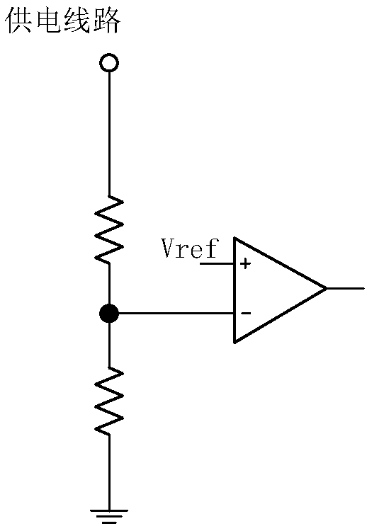
The invention provides an electric leakage protection circuit and method and an applicative driving device. The electric leakage protection circuit is used for achieving electric connection with a power supply line of a load, conducting spaced sampling on the power supply line, detecting the voltage of a sample electric signal so as to determine whether the voltage of an alternating-current inputpower supply is divided or not, and providing electric leakage protection based on determined results. The electric leakage protection circuit determines whether the voltage of the connected alternating-current input power supply is divided or not through spaced sampling conducted on the voltage of the power supply line and voltage dividing detection. When voltage division is determined, the powersupply line is disconnected, and electric leakage protection of the human body mistakenly undergoing electric shock and the load is achieved.

Description

technical field [0001] The present application relates to the technical field of electronic circuits, in particular to a leakage protection circuit, a method and an applicable driving device. Background technique [0002] When people insert one end of the LED fluorescent tube into the slot of the fluorescent tube frame, people may focus on assembling the needle-like pins of the LED fluorescent lamp and ignore the position of the handheld lamp. When one end of the fluorescent lamp is inserted into the slot of the fluorescent tube frame, the There is a danger of electric shock by touching the other end of the LED fluorescent lamp that is not inserted into the slot on the fluorescent tube frame with your finger. Contents of the invention [0003] In view of the shortcomings of the prior art described above, the purpose of this application is to provide a leakage protection circuit, method and applicable driving device for solving the problem of leakage caused by accidental co...

Claims


Application Information

Patent Timeline
Patent Type & Authority Applications(China)
IPC IPC(8): H02H3/32H05B33/08H05B44/00H05B45/50
CPCH02H3/325H05B45/00H05B45/50G01R31/40G01R31/52Y02B20/30H05B45/345H05B45/36H05B45/395F21V25/04F21K9/272G01R31/44H05B45/37
Inventor 孙顺根郁炜嘉
Owner SHANGHAI BRIGHT POWER SEMICONDUCTOR CO LTD
Learn More