High-heeled shoes with support frames
A technology for high-heeled shoes and heels, applied in footwear, clothing, applications, etc., can solve the problems of uncomfortable, unhygienic, and inconvenient heels and soles, and achieve the effects of improving comfort, convenient operation, and simple structure
- Summary
- Abstract
- Description
- Claims
- Application Information
AI Technical Summary
Problems solved by technology
Method used
Image
Examples
Embodiment 1
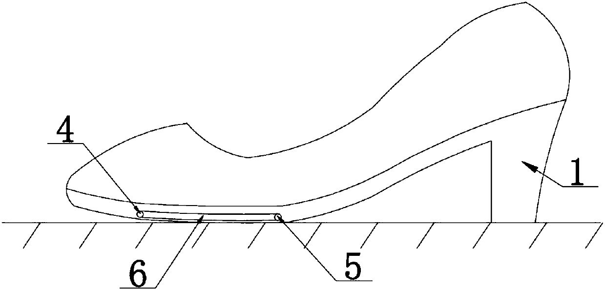
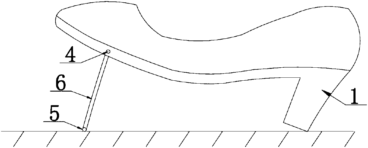
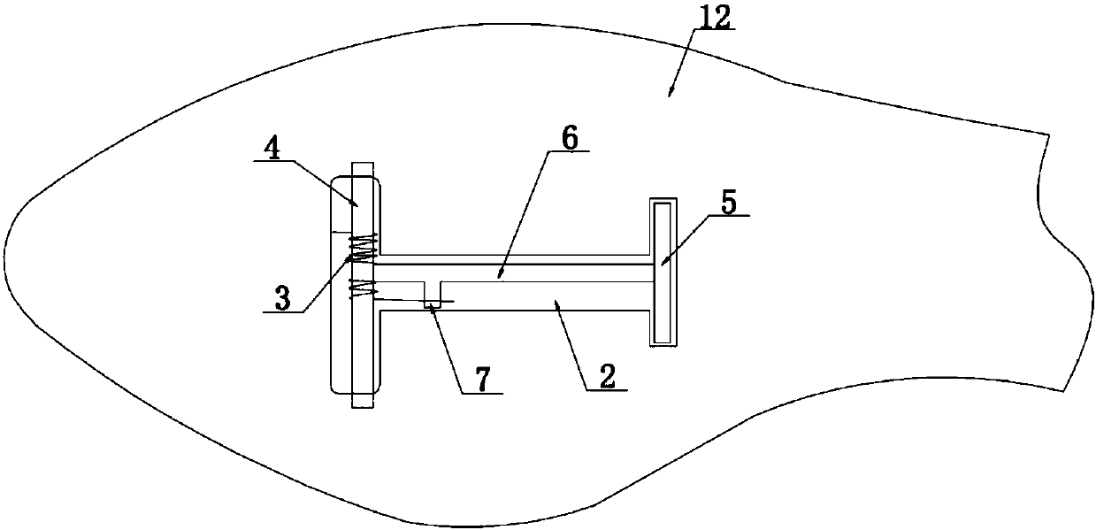
[0024] Example 1, such as Figure 1-Figure 3 As shown, a high-heeled shoe with a bracket includes a heel portion and a sole portion, the heel portion is provided with a heel 1, and also includes a supporting mechanism arranged on the sole portion, and the bottom portion of the sole portion is provided with a Place the accommodating groove 2 of the supporting mechanism, the supporting mechanism includes a supporting body and a torsion spring 3, the supporting body includes a rotating shaft 4 arranged at the front, a supporting part 5 arranged at the rear, and is used to connect the rotating shaft and the supporting part The connecting part 6 and the torsion spring pressing part 7 arranged on the connecting part, the torsion spring is wound and sleeved on the outside of the rotating shaft, and the inner and outer sides of the accommodating groove are provided for limiting the end of the rotating shaft. One end of the torsion spring is supported on the accommodating groove, and t...
Embodiment 2
[0026] Example 2, such as Figure 4 As shown, the free end of the torsion spring pressing part is provided with an operating handle 8, the operating handle protrudes from the sole of the foot, and the sole of the foot is provided with a guide groove 9 for accommodating the operating handle. Generally, the operating handle should be located on the inside of the shoe. When walking in high-heeled shoes, the support body exerted by the torsion spring is laid flat in the storage tank, and the support body will not be put down due to the force of the torsion spring, which can ensure a stable walking process; once you sit down, you can manually lift the support body by The accommodating groove is turned inside out, and the rear end of the supporting body is supported on the ground. Because the feet have a certain pressure on the supporting body, the soles of the feet can be supported against the force of the torsion spring, so that the soles of the feet after sitting down are more co...
Embodiment 3
[0027] Example 3, such as Figure 5 with Image 6 As shown, a limit mechanism is provided in the accommodating groove, and the limit mechanism includes a support shaft 10 and a stopper 11 for limiting the support portion, and the support shaft is installed on the sole of the foot. At the bottom, the blocking piece is rotatably mounted on the support shaft. The front end of the support body is limited by the function of the rotating shaft and the installation hole, while the rear end of the support body is limited in the accommodating groove by the force of the torsion spring on the pressure part of the torsion spring. In the case of sudden lowering of the middle support body, a stopper is installed at the rear end of the support body. During walking, the stopper can be turned to the bottom of the support part to support the support body. When sitting down, the stopper can be turned to a position that does not affect the support body. Side, to further improve the support mech...
PUM
 Abstract
Description
Claims
Application Information
 - R&D
- Intellectual Property
- Life Sciences
- Materials
- Tech Scout
- Unparalleled Data Quality
- Higher Quality Content
- 60% Fewer Hallucinations
Browse by: Latest US Patents, China's latest patents, Technical Efficacy Thesaurus, Application Domain, Technology Topic, Popular Technical Reports.
© 2025 PatSnap. All rights reserved.Legal|Privacy policy|Modern Slavery Act Transparency Statement|Sitemap|About US| Contact US: help@patsnap.com


