
Winding mechanism for pulling adhesive tape

A sticky tape and sticky tape technology, which is applied in the manufacture of inductors/transformers/magnets, electrical components, circuits, etc., can solve problems such as uneven pulling force by manpower, performance that cannot meet the design requirements, and difficulty in guaranteeing the quality of sticky tapes, etc. , to achieve the effect of improving work efficiency and sticky tape quality, concise structure, and easy design and manufacture

Pending Publication Date: 2018-02-02
SHANDONG DACHI ELECTRIC
View PDF0 Cites 0 Cited by
  • Summary
  • Abstract
  • Description
  • Claims
  • Application Information

AI Technical Summary

Problems solved by technology

[0003] At present, after the transformer core is stacked, in order to firmly tighten the iron core laminations, the production of adhesive tapes is generally done manually. Not only does it need to make a winding template, two or three people work together, and the manual pulling force is not uniform. The quality of sticky tape is difficult to guarantee, and some of its performance cannot meet the design requirements
Some operators have also come up with various methods, but this problem has not been solved well so far, so that the operators still use the old way to manually pull and wind

Method used


Image

  • Winding mechanism for pulling adhesive tape
  • Winding mechanism for pulling adhesive tape
  • Winding mechanism for pulling adhesive tape

Examples


Embodiment Construction

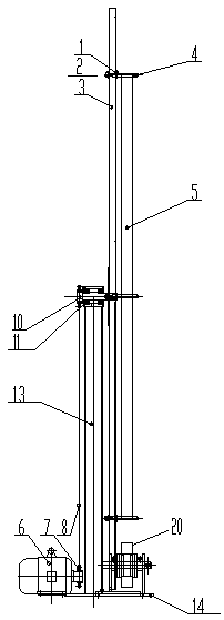
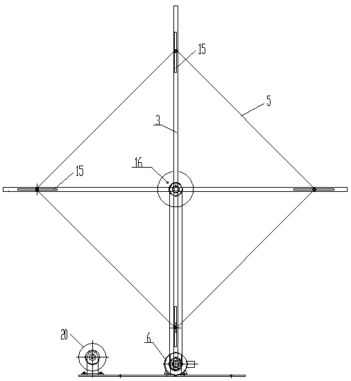
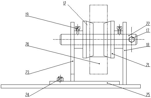
[0024] Accompanying drawing is a kind of embodiment of the present invention.

[0025] The adhesive tape winding mechanism of the present invention includes a frame, and a motor 6, a transmission device and a winding device installed on the frame and sequentially connected, and also includes an adhesive tape taking device installed on the frame;

[0026] The rack is fixed on the ground;

[0027] Winding device comprises cross support 3, and the intersection of cross support is connected transmission device, and a strut 4 is all installed on the four arms of cross support, and four struts form the four corners of a square, and the sticky tape that disc adhesive tape 20 emits follows The rotation of the cross bracket is wound on a square formed by four struts, and the adhesive tape is wound into an annular adhesive tape 5 with a certain thickness and a suitable size;

[0028] The adhesive tape taking device adopts an adhesive tape reel support frame, and the disc adhesive tape ...


PUM


Abstract

The invention discloses a winding mechanism for pulling adhesive tape. The winding mechanism is characterized by comprising a rack, a motor, a drive device and a winding device and further comprisingan adhesive tape taking device, wherein the motor, the drive device and the winding device are installed on the rack and sequentially connected, and the adhesive tape taking device is installed on therack; the rack is fixed to the ground; the winding device comprises a cross-shaped support, the drive device is connected to the crossing position of the cross-shaped support, four supporting rods are installed on four arms of the cross-shaped support respectively and form a square with four corners, and the adhesive tape part which is paid off by the disc adhesive tape will be wound around the square formed by the four supporting rods along with rotation of the cross-shaped support; an adhesive tape disc supporting frame is adopted for the adhesive tape taking device, and the disc adhesive tape is installed on the adhesive tape disc supporting frame in a rotatable mode. The winding mechanism has the advantages that manual taking and pulling are replaced, it is not needed to manufacture winding templates of all models, the winding mechanism can be operated by only one person, pulling force is even in mechanical winding, the quality of the manufactured adhesive tape is guaranteed, properties meet designing requirements, meanwhile, operation efficiency is improved, and labor intensity is relieved to a certain degree.

Description

[0001] (1) Field [0002] The invention relates to a sticky tape winding mechanism, which belongs to a device for making sticky tapes required for firmly tightening the iron core laminations after the transformer cores are stacked. (2) Background technology [0003] At present, after the transformer core is stacked, in order to firmly tighten the iron core laminations, the production of adhesive tapes is generally done manually. Not only does it need to make a winding template, two or three people work together, and the manual pulling force is not uniform. The quality of the adhesive tape is difficult to guarantee, and some of its performance cannot meet the design requirements. Some operators have also come up with various methods, but this problem has not been solved well at present, so that the operators still use the old way to manually pull and wind. This operation is a necessary process for core stacking, and each set repeats the same work, so such a practical improveme...

Claims


Application Information

Patent Timeline
Patent Type & Authority Applications(China)
IPC IPC(8): H01F41/00
CPCH01F41/00
Inventor 郝敬志付桂芹王艳艳郝敬荣祝虎
Owner SHANDONG DACHI ELECTRIC
Learn More