
Method for controlling condensate gas reservoir mist retrograde condensation

A technology for condensate gas reservoirs and control methods, which is applied in the field of foggy reverse condensate control in condensate gas reservoirs, can solve the problems of large investment and low condensate oil recovery, and achieve high recovery and good recovery Condensation effect, reduce the effect of anti-condensation

Inactive Publication Date: 2018-01-23
CHINA PETROLEUM & CHEM CORP
View PDF4 Cites 2 Cited by
  • Summary
  • Abstract
  • Description
  • Claims
  • Application Information

AI Technical Summary

Problems solved by technology

[0007] The present invention provides a control method for foggy reverse condensate in condensate gas reservoirs, which overcomes the deficiencies of the prior art and can effectively solve the problems of large investment and poor condensate oil recovery in the existing reverse condensate control technology. high problem

Method used


Image

  • Method for controlling condensate gas reservoir mist retrograde condensation
  • Method for controlling condensate gas reservoir mist retrograde condensation
  • Method for controlling condensate gas reservoir mist retrograde condensation

Examples


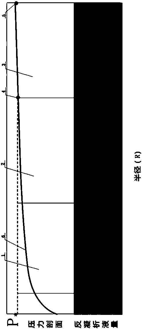
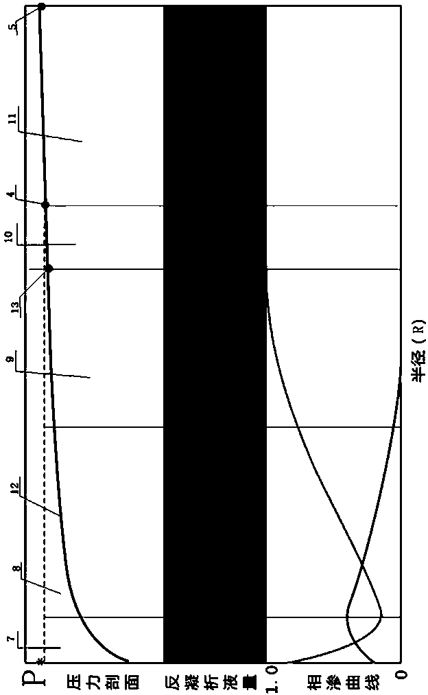
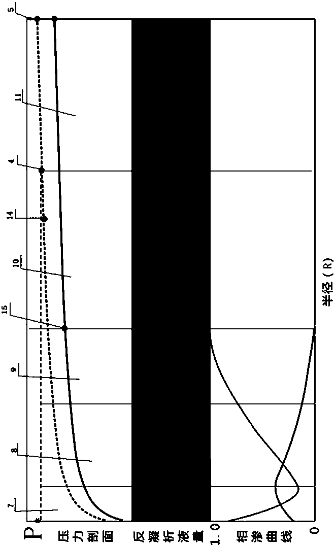
Embodiment 1

[0027] Embodiment 1: The control method of foggy reverse condensate in the condensate gas reservoir is controlled according to the following method: the gas production rate is 3% to 8%, the well spacing is 400m to 1400m, and the production pressure difference is 0.5MPa to 2.2 MPa.

[0028] Through the control of gas production speed, well spacing and production pressure difference, it is possible to control the reverse condensate oil in the gas reservoir to always be in the form of mist (dispersion), and to form and recover at any time, so as to achieve foggy reverse condensate and foggy reverse condensate Oil flow output, reduce retrocondensation.

[0029] Since the method of the present invention is not a development method of gas injection and pressure maintenance, there is no need to build corresponding gas injection supporting facilities, so that no corresponding investment funds are required. The method requires less investment.

[0030] There are three control paramet...

Embodiment 2

[0036] Embodiment 2: The control method of misty retrocondensation in the condensate gas reservoir is controlled according to the following method: the gas production rate is 3% or 8%, the well spacing is 400m or 1400m, and the production pressure difference is 0.5MPa or 2.2 MPa.

Embodiment 3

[0037] Embodiment 3: As an optimization of the above embodiment, when the gas reservoir is a high-porosity and high-permeability condensate gas reservoir, the well spacing of vertical wells is 900m to 1250m, and the well spacing of horizontal wells is 1300m to 1400m.

[0038] For condensate gas reservoirs in high-porosity and high-permeability reservoirs, the vertical well spacing and horizontal well spacing are set so that the control ranges of each well overlap and can realize foggy reverse condensation in condensate gas reservoirs in high-porosity and high-permeability reservoirs. Reduce the occurrence of retrocondensation.


PUM


Abstract

The invention relates to the technical field of condensate gas reservoir retrograde condensation controlling, and discloses a method for controlling condensate gas reservoir mist retrograde condensation. Controlling is conducted according to the following method that the gas producing rate, the well spacing and the differential pressure of production are controlled. According to the method for controlling condensate gas reservoir mist retrograde condensation, aiming at different condensate gas reservoir conditions, gas reservoir retrograde condensation oil is controlled to be always in a mistform, forming and extraction are conducted at any time, so that the purpose that retrograde condensation is reduced is achieved, a better retrograde condensation effect can be achieved, the recovery ratio is high and higher than 67.8%, the investment is low when mining is conducted by using the method for controlling condensate gas reservoir mist retrograde condensation, and a new path is providedfor a retrograde condensation controlling technology under a condensate gas reservoir exhaustion development mode.

Description

technical field [0001] The invention relates to the technical field of anti-condensation control of condensate gas reservoirs, and relates to a method for controlling foggy anti-condensation of condensate gas reservoirs. Background technique [0002] The original formation pressure of condensate gas reservoirs is generally higher than the dew point pressure. Under the initial conditions, natural gas and condensate oil are in a single gas phase state. During the depletion production process, when the formation pressure is lower than the dew point pressure, retrograde condensation will occur Phenomenon, the condensate oil will be separated from the gas phase to form two phases of gas and liquid, and part of it will remain in the reservoir, resulting in the loss of condensate oil [0003] When the bottomhole flowing pressure is higher than the dew point pressure, the entire formation is in a single-phase gas flow state; when the bottomhole flowing pressure is lower than the dew...

Claims


Application Information

Patent Timeline
Patent Type & Authority Applications(China)
IPC IPC(8): E21B43/30E21B47/06E21B43/00
Inventor 李宗宇何云峰梁静献姚田万袁锦亮徐士胜张艾王利刚丁卫平张奎
Owner CHINA PETROLEUM & CHEM CORP
Learn More